background image

5-4  

USER INTERFACE

Models C709 & C717

User Interface 

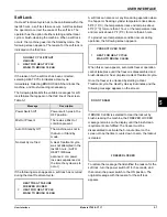
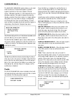
Language Initialization

The UVC platform supports multiple languages by 

keeping specific strings in the battery-backed RAM. After 

power-up or a CPU reset, the strings are tested to see if 

they are present and not corrupted. If the strings are 

present and not corrupted, initialization continues. 

Otherwise, the operator is prompted to select a 

language. While language strings are being checked for 

integrity, the following screen appears.

Note:  

If there is a language initialization fault, the 

machine forces a language selection prior to the 

initializing sequence. The standard menu LEDs should 

light as if they were in a menu. If a language has been 

selected, the machine is powered down, and the 

machine should not ask for a language unless there is 

another language initialization fault. English is the factory 

default setting.

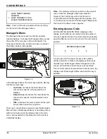
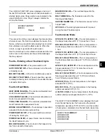
System Data

System data is protected separately from the rest of the 

data in memory. System data includes variables that 

change frequently, such as the machine’s mode, lockout 

status, serving counters, and fault codes. While system 

data is being checked, the following screen appears.

If the system data is corrupted, the machine is set to Off, 

the serving counters are set to zero, and the faults are 

cleared. A SYSTEM CRC ERR fault is set and displayed 

on the VFD. An acknowledgment (SEL key) is required.

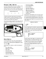
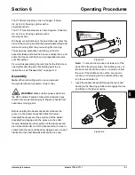
Configuration Data

Configuration data is separate from the rest of the data in 

the memory. Configuration data is information entered 

through operator and service menus. While configuration 

data is being checked, the following screen appears.

If configuration data is corrupted, all user and service 

settings are set to defaults. A CONFIG CRC ERR fault is 

displayed on the VFD. The system continues to operate 

in its previous mode, but with default settings.

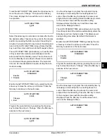
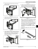
Lockout Data

Lockout data is protected separately from the rest of the 

data in the memory. While the lockout data is being 

checked, the following screen appears.

If lockout data is corrupted, all lockout history data is 

cleared. A LOCKOUT CRC ERR fault appears.

After the memory integrity has been tested, the Safety 

Timeout screen appears.

Heat Cycle Data

Heat cycle data is checked separately from the rest of the 

data in memory. Each individual Heat cycle data record is 

monitored for corruption individually. At the start of a Heat 

cycle, the next Heat cycle data record is cleared, and 

data for the Heat cycle is written to it. The current Heat 

cycle data appears as the first Heat cycle record in the 

HEAT CYCLE DATA menu option.

The Heat cycle data records are checked for integrity 

when the record is accessed, but presently only through 

the HEAT CYCLE DATA menu option.

Initializing
Language

Initializing
System Data

Initializing
Config Data

Initializing
Lockout Data

Summary of Contents for C709

Page 1: ...OPERATOR S MANUAL Model C709 and C717 Heat Treatment Soft Serve Freezers Original Operating Instructions 062080 M 2 4 05 Original Publication Updated 11 8 2019...

Page 2: ...ycle__________ Phase__________________________________ Maximum Fuse Size ______________________________________________________ A Minimum Wire Ampacity ________________________________________________...

Page 3: ...r Compressor Warranty Disclaimer 2 2 Section 3 Safety Section 4 Parts Model C709 4 1 Model C709 Single Spout Door and Beater Assembly 4 2 Model C717 4 3 Model C717 Three Spout Door and Beater Assembly...

Page 4: ...Procedures 6 10 Manual Brush Cleaning 6 11 Draining Product from the Freezing Cylinder 6 11 Rinsing 6 11 Hopper Cleaning 6 12 Disassembly 6 12 Brush Cleaning 6 12 Section 7 Operator s Checklist During...

Page 5: ...w this instruction may result in personal injury or death from electrical shock or hazardous moving parts as well as poor performance or damage to the machine WARNING This machine has many sharp edges...

Page 6: ...t fitting to an open trap drain IMPORTANT A backflow prevention device is required on the incoming water connection side Please see the applicable national state and local codes for determining the pr...

Page 7: ...main control box located behind the service panel It is recommended that beater rotation adjustment be performed by an authorized Taylor service technician Refrigerant CAUTION This machine contains fl...

Page 8: ...1 4 TO THE INSTALLER Models C709 C717 To the Installer 1 Notes...

Page 9: ...authorized Taylor distributor and only if all required service work is provided by a Taylor service technician Taylor reserves the right to deny warranty claims on machines or parts if Taylor unapprov...

Page 10: ...void To find out the current status of an alternate refrigerant as it relates to your compressor warranty call the local Taylor distributor or the Taylor factory Be prepared to provide the model seri...

Page 11: ...ere a water jet could be used Failure to follow this instruction may result in serious electrical shock WARNING Avoid injury DO NOT operate the machine unless it is properly grounded DO NOT operate th...

Page 12: ...federal state or local regulatory agencies and must be followed accordingly Please refer to the cleaning section of this manual for the proper procedure to clean this machine Do not run the machine wi...

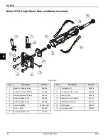
Page 13: ...r CVR 043934 4 Kit A Cover Hopper X65368 5 Blade A Agitator X56591 6 Tube A Feed Outer HT X34641 7 Panel Rear 056077 SP1 8 Orifice 022465 100 9 Screw 1 4 20X3 8 RHM SS 011694 Item Description Part No...

Page 14: ...W 50 015872 3 Screw Adjustment 5 16 24 056332 4 Nut Stud Black 3 250 058765 5 Nut Stud Black 2 563 058764 6 Door A w Baffle X57332 SER 7 Valve A Draw X55820 8 O ring Draw Valve S S 014402 Item Descrip...

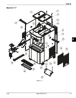
Page 15: ...PARTS 4 3 Models C709 C717 Parts 4 Model C717 Figure 4 3 9 25 1 3 4 5 6 7 8 9 13 15 16 17 24 21 23 22 19 2 18 26 10 11 12 14 20...

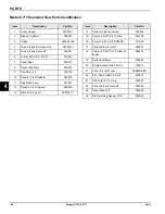
Page 16: ...dle X63879 11 Stud Nose Cone 055987 12 Panel A Front Upper X59836 13 Filter Air Poly FLO 052779 11 Item Description Part No 14 Panel A Filter Louvered X59928 15 Caster 4 SWV 3 4 10 Stem 044106 16 Scre...

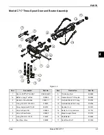
Page 17: ...ring 1 4 OD X 070W 50 015872 4 Screw Adjustment 5 16 24 056332 5 Valve A Draw L R X59888 6 Valve A Draw Center X59890 7 O ring 7 8 OD X 103W 014402 8 Seal Draw Valve 034698 Item Description Part No 9...

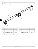
Page 18: ...2 1a 1 3 5 Item Description Part No 1 Air Orifice 022465 100 1a O ring 016137 2 Tube A Feed SC Inner C709 X32824 2 Tube A Feed SC Inner C717 X32824 3 Item Description Part No 3 O ring 291 ID x 080 W 0...

Page 19: ...ropriate Taylor approved food safe lubricant HP 1 2 3 Item Description Part No 1 Pail 10 qt 013163 2 Tool O ring Removal 048260 WHT 3 Lubricant Taylor Hi Perf 048232 Item Description Part No 4 Sanitiz...

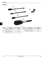
Page 20: ...hes Figure 4 7 1 2 3 4 5 Item Description Part No 1 Brush Rear BRG 1 D X 2 L 013071 2 Brush Double Ended 013072 3 Brush Draw Valve 1 OD X 2 013073 Item Description Part No 4 Brush Mix Pump Body 3 X 7...

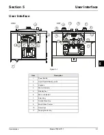
Page 21: ...5 1 Item Description 1 Power Switch 2 Liquid Crystal Display LCD 3 Keypads 4 Mix Out Indicator 5 Standby Key 6 Mix Low Indicator 7 Select Key 8 Service Menu Key 9 Brush Clean Counter 10 Arrow Keys 11...

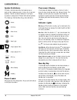
Page 22: ...placed in the Standby mode To initiate the refrigeration system add mix to the mix hopper and press the Auto key The freezer automatically begins operation Heat Mode When the Heat Cycle key is illumin...

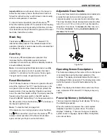
Page 23: ...ace the power switch in the OFF position Press the RESET button firmly Turn the power switch to the ON position Press the Wash key and observe the freezer s performance Note To clear the fault see pag...

Page 24: ...fault is set and displayed on the VFD An acknowledgment SEL key is required Configuration Data Configuration data is separate from the rest of the data in the memory Configuration data is information...

Page 25: ...key to immediately start a Heat cycle Note The machine must be in Auto or Standby mode and have sufficient mix in the hopper before the machine can successfully enter the Heat mode of operation Heat C...

Page 26: ...ne to be disassembled and brush cleaned A soft lock can be corrected by either disassembling and brush cleaning the machine or by starting another Heat Treatment cycle Hard Lock There are two causes o...

Page 27: ...When this screen appears automatic freezer operation cannot take place until the freezer is disassembled and brush cleaned or has completed a Heat Treatment cycle Once the freezer is unlocked by start...

Page 28: ...iod the display exits to the main menu One exception to this timeout is for the Current Conditions display Note The machine continues operation in the mode it was in when the Manager s Menu was select...

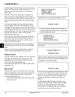
Page 29: ...OPERATION MIX LEVEL AUDIBLE FAULT DESCRIPTION FAULT HISTORY LOCKOUT HISTORY HEAT CYCLE SUMMARY HEAT CYCLE DATA SYSTEM INFORMATION CURRENT CONDITIONS ENABLE WIFI Selecting EXIT FROM MENU exits the Man...

Page 30: ...Down arrow key to move the arrow to the appropriate month for the start of DST Pressing the SEL key with the arrow next to the appropriate month displays the following screen Press the Up or Down arro...

Page 31: ...eys to program the auto start time by increasing or decreasing the hour setting above the cursor Press the SEL key to advance the cursor and program the minutes setting Select the SEL key to return to...

Page 32: ...r s Menu screen Listed below are the variable messages that appear along with an explanation for the corrective action NO FAULT FOUND There was no fault found in the freezer Nothing appears on the scr...

Page 33: ...failure occurred during the Heat Treatment cycle MIX LOW FAILURE The mix level in the hopper is too low for a successful Heat cycle BEATER OVLD H C The overload tripped for the beater motor BRL THERM...

Page 34: ...lays the amount of time that the hopper was greater than the Hold temperature Line 4 displays the time spent in the Heat and Cool phases for the barrel and the peak barrel temperature through the enti...

Page 35: ...y functional Exit the Current Conditions screen and return to the Manager s Menu by pressing the SEL key ENABLE WIFI The ENABLE WIFI screen provides the ability to enable disable the WIFI gateway if t...

Page 36: ...5 16 USER INTERFACE Models C709 C717 User Interface 5 Notes...

Page 37: ...the power switch is in the OFF position Failure to follow this instruction may result in severe personal injury to fingers or hands from hazardous moving parts Before installing the beater driveshaft...

Page 38: ...mainder of the way into the freezing cylinder and over the end of the driveshaft The beater should fit snugly but not so tightly that the beater cannot be turned slightly to engage the driveshaft If t...

Page 39: ...ing down Slide the fork of the draw handle into the slot of the draw valve Secure with the pivot pin Figure 6 10 Note The C709 features an adjustable draw handle to provide portion control giving a be...

Page 40: ...icate the gaskets or bearings Figure 6 14 3 Insert the baffle rods through the beaters in the freezing cylinders With the door seated on the freezer studs install the handscrews with the longer handsc...

Page 41: ...rtion control giving a more consistent quality to your product and controlling costs The draw handles should be adjusted to provide a flow rate of 5 oz to 7 1 2 oz 142 g to 213 g of product by weight...

Page 42: ...enlarge the hole in the air orifice 4 Lay the inner feed tube the outer feed tube and the agitator in the bottom of the mix hopper for sanitizing Figure 6 25 5 Repeat steps 1 through 4 for the other...

Page 43: ...ner feed tube inside the outer feed tube Figure 6 28 9 Install the air orifice into the hole in the top of the inner feed tube Figure 6 29 Note Make sure the hole in the air orifice is clean and is no...

Page 44: ...d then bringing the temperature back down low enough to delay spoilage The Heat Treatment cycle starts at the time designated in the Auto Heat Time Important The level of mix in the mix hopper s must...

Page 45: ...nitized towel wipe down the freezer door front panel the area around the bottom of the freezer door and any other areas with a buildup of either moisture or food substance The Heat cycle starts when t...

Page 46: ...he draw valve s Figure 6 35 Note To ensure sanitary conditions are maintained brush clean each item for 60 seconds repeatedly dipping the brush in sanitizing solution 4 Using a clean sanitized towel w...

Page 47: ...rain the product from the freezing cylinder and mix hopper and properly dispose of the mix 4 When the flow of product stops press the Wash key canceling the Wash mode Close the draw valve 5 Repeat ste...

Page 48: ...mber of days allowed between brush clean cycles or the machine will hard lock and will not operate 1 Make sure the power switch is in the OFF position 2 Remove the handscrews freezer door beater scrap...

Page 49: ...ezer with a small amount of cleaning solution Using the black brush clean the rear shell bearing at the back of the freezing cylinder Figure 6 42 6 Repeat steps 1 through 5 for the other side of Model...

Page 50: ...6 14 OPERATING PROCEDURES Models C709 C717 Operating Procedures 6 Notes...

Page 51: ...ing and sanitizing solutions Read and follow label directions carefully Too strong of a solution may damage the parts and too weak of a solution does not adequately clean or sanitize The temperature o...

Page 52: ...ining in the condenser This is extremely important Failure to follow this procedure may cause severe and costly damage to the refrigeration system Your local Taylor distributor can perform this winter...

Page 53: ...y mode The freezer must be disassembled and brush cleaned or placed in a Heat cycle 5 7 d Mix Out condition d Level of mix in hopper must be up to the fill line on the agitator paddle The freezer must...

Page 54: ...e air cooled machines b Allow for adequate airflow across the condenser 1 2 c Worn scraper blades c Replace regularly 9 1 d Dirty condenser A C d Clean monthly 7 1 e Mix is out of date e Use only fres...

Page 55: ...The freezing cylinder walls are scored a Missing or worn front bearing and scraper blades a Install or replace the front bearing and scraper blades 6 2 b The baffle rod on the freezer door is broken...

Page 56: ...8 4 TROUBLESHOOTING GUIDE Models C709 C717 Troubleshooting Guide 8 Notes...

Page 57: ...t X Front Bearing X Draw Valve O ring X Mix Feed Tube O ring X Air Orifice O ring X White Bristle Brush 3 x 7 Inspect and replace if necessary Minimum White Bristle Brush 1 x 2 Inspect and replace if...

Page 58: ...9 2 PARTS REPLACEMENT SCHEDULE Models C709 C717 Parts Replacement Schedule 9 Notes...

Page 59: ...ED WARRANTY CONDITIONS 1 If the date of original installation of the Product cannot be verified then the limited warranty period begins ninety 90 days from the date of Product manufacture as indicated...

Page 60: ...irs due to theft vandalism wind rain flood high water water lightning earthquake or any other natural disaster fire corrosive environments insect or rodent infestation or other casualty accident or co...

Page 61: ...AL OR INCIDENTAL DAMAGES INCLUDING CLAIMS FOR LOST SALES LOST PROFITS PRODUCT LOSS PROPERTY DAMAGES OR SERVICE EXPENSES ARE EXPRESSLY EXCLUDED THE EXPRESS WARRANTIES MADE IN THIS LIMITED WARRANTY MAY...

Page 62: ...10 4 LIMITED WARRANTY ON EQUIPMENT Models C709 C717 Limited Warranty on Equipment 10 Notes...

Page 63: ...ified proof of purchase may be required at time of service 2 This limited warranty is valid only if the Part is installed and all required service work in connection with the Part is performed by an a...

Page 64: ...g warranty service work promptly upon arrival 9 Failure damage or repairs due to faulty installation misapplication abuse no or improper servicing unauthorized alteration or improper operation or use...

Page 65: ...R INCIDENTAL DAMAGES INCLUDING CLAIMS FOR LOST SALES LOST PROFITS PRODUCT LOSS PROPERTY DAMAGES OR SERVICE EXPENSES ARE EXPRESSLY EXCLUDED THE EXPRESS WARRANTIES MADE IN THIS LIMITED WARRANTY MAY NOT...

Page 66: ...11 4 LIMITED WARRANTY ON PARTS Models C709 C717 Limited Warranty on Parts 11 Notes...

Reviews: