background image

44

Models C709 & C717

Operating Procedures

080227

Step 3

Open the draw valve on the freezer door. Drain all
the rinse water from the door spout, close the draw

valve and touch the WASH symbol,

/

cancelling

the Wash mode.

Step 4

Repeat this procedure using clean, warm water, until
the water being discharged is clear.

Repeat these steps for the other side of the
C717.

Hopper Cleaning

Step 1

Prepare an approved 100 PPM cleaning solution
(examples: 2-1/2 gal. [9.5 liters] of Kay-5

R

or 2

gal. [7.6 liters] of Stera-Sheen

R

). USE WARM

WATER AND FOLLOW THE MANUFACTURER'S
SPECIFICATIONS.

Step 2

Pour the solution into the hopper and allow it to flow
into the freezing cylinder.

Step 3

Using the white hopper brush, clean the mix hopper,
mix level sensing probes and the outside of the
agitator drive shaft housing. Using the double ended
brush, clean the mix inlet hole. (

Note:

Do not brush

clean the mix inlet hole while the machine is in the
Wash mode.)

Step 4

Touch the WASH symbol

/

. This will cause the

cleaning solution in the freezing cylinder to come in
contact with all areas of the freezing cylinder.

Step 5

Place an empty pail beneath the door spout(s).

Step 6

Open the draw valve on the freezer door and draw
off all the solution.

Step 7

Once the cleaning solution stops flowing from the
door spout, close the draw valve and touch the

WASH symbol

/

, cancelling the Wash mode.

Repeat these steps for the other side of the
C717.

Disassembly

Note:

Failure to remove the parts specified below

for brush cleaning and lubrication will result in
damage to the machine. These parts must be
removed within the maximum number of days
allowed between brush clean cycles or the machine
will hard lock and will not operate.

Step 1

Be sure the power switch is in the OFF position.

Step 2

Remove the handscrews, freezer door, beater and
scraper blades, and drive shaft with drive shaft seal
from the freezing cylinder.

Step 3

Remove the scraper blades.

Step 4

Remove the drive shaft seal from the drive shaft.

Step 5

Remove the freezer door gasket, front bearing, pivot
pin, draw handle, and draw valve. Remove the three
o-rings from the draw valve.

Step 6

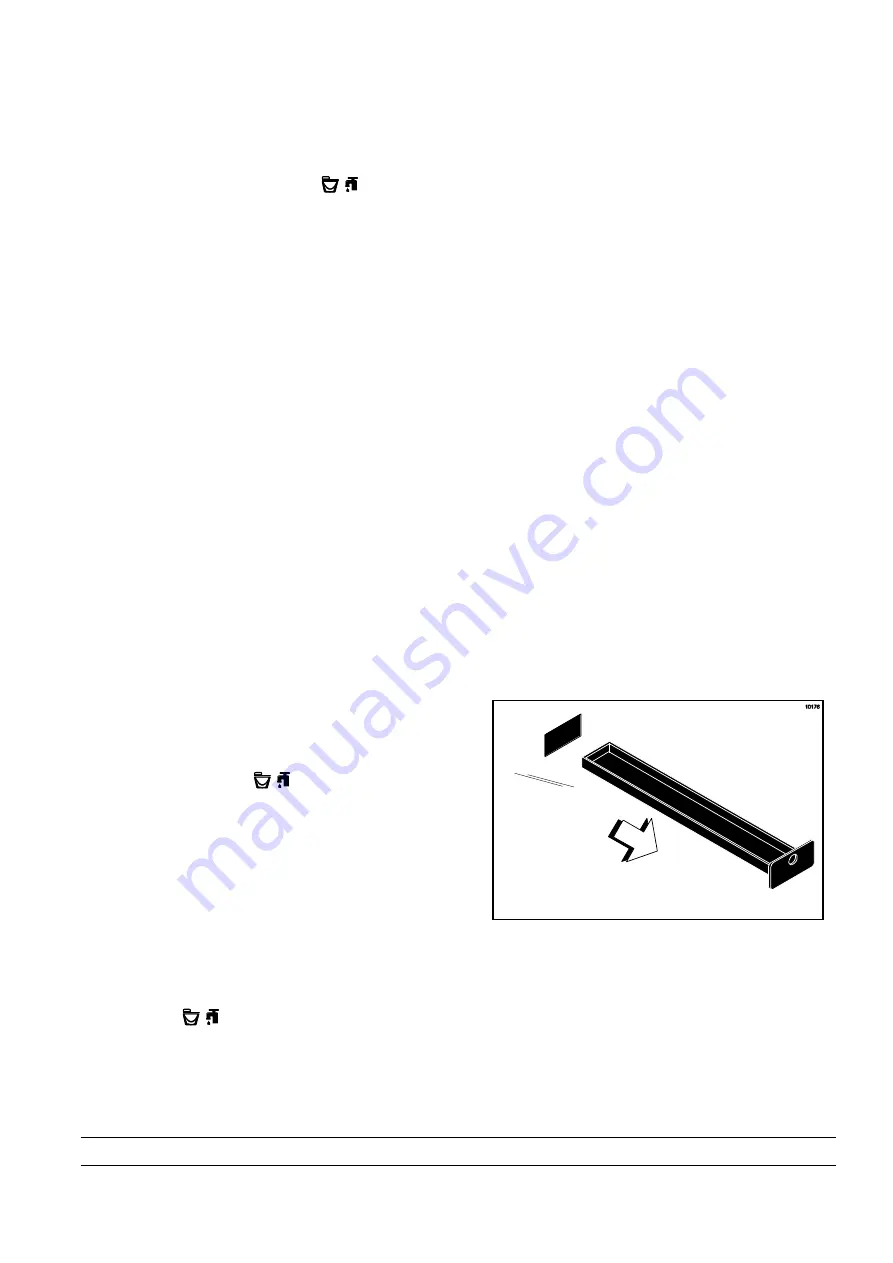
Remove the front drip tray and splash shield.

Step 7

Remove all drip pans and take them to the sink for
cleaning.

Figure 52

Note:

If the drip pans are filled with an excessive

amount of mix, it is an indication that the drive shaft
seal(s), or o-ring(s) should be replaced or properly
lubricated.

Repeat these steps for the other side of the
C717.

Summary of Contents for C709

Page 1: ...OPERATOR S MANUAL Model C709 C717 Heat Treatment Soft Serve Freezers Original Operating Instructions 062080 M 2 4 05 Original Publication Updated 9 2 14 ...

Page 2: ...mmercial Refrigeration Inc 062080 M Any unauthorized reproduction disclosure or distribution of copies by any person of any portion of this work may be a violation of Copyright Law of the United States of America and other countries could result in the awarding of Statutory Damages of up to 250 000 17 USC 504 for infringement and may result in further civil and criminal penalties All rights reserv...

Page 3: ...r Parts Identification 7 Model C709 7 Model C709 Single Spout Door and Beater Assembly 8 Model C717 9 Model C717 Three Spout Door and Beater Assembly 11 Feed Tube Assembly 12 Accessories 13 Brushes 14 Section 5 Important To the Operator 15 Symbol Definitions 16 Operating Screen Descriptions 18 Freezer Locks 20 Manager s Menu 22 Section 6 Operating Procedures 31 Assembly 31 Freezer Door Assembly 32...

Page 4: ...nformation in this manual is subject to change without notice Note Only instructions originating from the factory or its authorized translation representative s are considered to be the original set of instructions E 2005 Carrier Commercial Refrigeration Inc Original Publication Updated September 2014 062080 M Any unauthorized reproduction disclosure or distribution of copies by any person of any ...

Page 5: ...med by an authorized Taylor Service Technician This unit has many sharp edges that can cause severe injuries Site Preparation Review the area where the unit will be installed before uncrating the unit Make sure all possible hazards to the user or equipment have been addressed For Indoor Use Only This unit is designed to operate indoors under normal ambient temperatures of 70_ 75_F 21_ 24_C The fre...

Page 6: ...ECTRICAL CODES Each unit requires one power supply for each data label on the unit Check the data label s on the freezer for branch circuit overcurrent protection or fuse circuit ampacity and other electrical specifications Refer to the wiring diagram provided inside of the electrical box for proper power connections CAUTION THIS EQUIPMENT MUST BE PROPERLY GROUNDED FAILURE TO DO SO CAN RESULT IN S...

Page 7: ...dous and must be handled with caution NEVER fill any refrigerant cylinder completely with liquid Filling the cylinder to approximately 80 will allow for normal expansion Use only R404A refrigerant that conforms to the AHRI standard 700 specification The use of any other refrigerant may expose users and operators to unexpected safety hazards Refrigerant liquid sprayed onto the skin may cause seriou...

Page 8: ...rective as well as other similar legislation in effect after August 13 2005 Therefore it must be collected separately after its use is completed and cannot be disposed as unsorted municipal waste The user is responsible for returning the product to the appropriate collection facility as specified by your local code For additional information regarding applicable local laws please contact the munic...

Page 9: ...ance This unit is provided with an equipotential grounding lug that is to be properly attached to the rear of the frame by the authorized installer The installation location is marked by the equipotential bonding symbol 5021 of IEC 60417 1 on both the removable panel and the equipment s frame DO NOT use a water jet to clean or rinse the freezer Failure to follow these instructions may result in se...

Page 10: ...ruction can result in personal injury to fingers or equipment damage Access to the service area of the unit is restricted to persons having knowledge and practical experience with the appliance in particular as far as safety and hygiene are concerned This freezer must be placed on a level surface Failure to comply may result in personal injury or equipment damage Cleaning and sanitizing schedules ...

Page 11: ...PPER CVR 043934 4 KIT A COVER HOPPER X65368 5 BLADE A AGITATOR X56591 6 TUBE A FEED OUTER HT X34641 7 PANEL REAR 056077 SP1 8 ORIFICE 022465 100 9 SCREW 1 4 20X3 8 RHM SS 011694 ITEM DESCRIPTION PART NO 10 PANEL A SIDE RIGHT X57871 11 PANEL A FRONT UPPER X59423 12 PANEL A FRONT LOWER X58955 13 STUD NOSE CONE 055987 14 SHELF TRAY DRIP 056076 15 TRAY DRIP 056858 16 SHIELD SPLASH 049203 17 TUBE A FEE...

Page 12: ...2 3 SCREW ADJUSTMT 5 16 24 056332 4 NUT STUD BLACK 3 250 058765 5 NUT STUD BLACK 2 563 058764 6 DOOR A W BAFFLE X57332 SER 7 VALVE A DRAW X55820 8 O RING DRAW VALVE S S 014402 ITEM DESCRIPTION PART NO 9 PIN HANDLE SS 055819 10 GASKET DOOR HT 4 DBL 048926 11 BEARING FRONT 050216 12 BEATER A 3 4 QT HELICORE X31761 13 BLADE SCRAPER PLASTIC 035174 14 SHAFT BEATER 056078 15 SEAL DRIVE SHAFT 032560 ...

Page 13: ...9 Models C709 C717 Operator Parts Identification 130129 Model C717 Figure 3 ...

Page 14: ... A FRONT MIDDLE X63879 11 PANEL A FRONT UPPER X59836 12 STUD NOSE CONE 055987 13 FILTER AIR POLY FLO 052779 11 ITEM DESCRIPTION PART NO 14 PANEL A FILTER LOUVERED X59928 15 CASTER 4 SWV 3 4 10 STEM 044106 16 SCREW 1 4 20 X 3 8 RHM SS 011694 17 PANEL CORNER FRONT R 063087 18 CASTER 4 SWV 3 4 10 STEM W BRAKE 046437 19 DEFLECTOR BLOWER 059929 20 SHIELD SPLASH WIRE 19 3 4 L 033813 21 PANEL A FRONT LOW...

Page 15: ... X 070W 50 015872 4 SCREW ADJUSTMENT 5 16 24 056332 5 VALVE A DRAW L R X59888 6 VALVE A DRAW CENTER X59890 7 O RING 7 8 OD X 103W 014402 8 SEAL DRAW VALVE 034698 ITEM DESCRIPTION PART NO 9 PIN HANDLE TWIN 059894 10 GASKET DOOR HT 4 DOUBLE 048926 11 NUT STUD BLACK 3 250 LONG 058765 12 NUT STUD BLACK 2 563 LONG 058764 13 BEARING FRONT 050216 14 BEATER A 3 4QT HELICORE X31761 15 BLADE SCRAPER PLASTIC...

Page 16: ...ly Figure 5 ITEM DESCRIPTION PART NO 1 AIR ORIFICE 022465 100 1a O RING 016137 2 TUBE A FEED SC INNER C709 X32824 2 TUBE A FEED SC INNER C717 X32824 3 ITEM DESCRIPTION PART NO 3 O RING 291 ID x 080 W 018550 4 TUBE A FEED OUTER HT X34641 5 O RING 643 OD x 077 W 018572 ...

Page 17: ... REMOVAL 048260 WHT 3 LUBRICANT TAYLOR HI PERF 048232 ITEM DESCRIPTION PART NO 4 SANITIZER KAY 5 25 PACKS SEE NOTE 5 KIT A TUNE UP C709 X49463 92 KIT A TUNE UP C717 X49463 79 Note A sample container of sanitizer is sent with the unit For reorders order Kay 5 part no 041082 200 packs or Stera Sheen part no 055492 100 2 oz packs Not Shown ...

Page 18: ...ification Brushes Figure 7 ITEM DESCRIPTION PART NO 1 BRUSH REAR BRG 1 D X 2 L 013071 2 BRUSH DOUBLE ENDED 013072 3 BRUSH DRAW VALVE 1 OD X 2 013073 ITEM DESCRIPTION PART NO 4 BRUSH MIX PUMP BODY 3 X 7 023316 5 BRUSH END DOOR SPOUT SS 039719 ...

Page 19: ...Section 5 Important To the Operator Figure 8 ITEM DESCRIPTION 1 POWER SWITCH 2 LIQUID CRYSTAL DISPLAY 3 KEYPADS 4 MIX OUT INDICATOR 5 STANDBY KEY 6 MIX LOW INDICATOR 7 SELECT KEY 8 SERVICE MENU KEY 9 BRUSH CLEAN COUNTER 10 ARROW KEYS 11 TOPPING HEATER KEY ...

Page 20: ...T When the MIX OUT symbol is illuminated the mix hopper has been almost completely exhausted and has an insufficient supply of mix to operate the freezer At this time the AUTO mode is locked out and the freezer will be placed in the STANDBY mode To initiate the refrigeration system add mix to the mix hopper and touch the AUTO symbol The freezer will automatically begin operation HEAT MODE When the...

Page 21: ... will shut off Reset Mechanism The C709 reset button is located in the service panel on the left side of the machine The C717 reset buttons are located in the rear panel of the machine Reset button s protect the beater motor s from an overload condition Should an overload occur the reset mechanism will trip To properly reset the freezer place the power switch in the OFF position Press the reset bu...

Page 22: ... machine will force a language selection prior to the initializing sequence The standard menu LED s should light as if it were in a menu If a language has been selected the unit is powered down the machine should not ask for a language unless there is another language initialization fault English is the factory default setting System Data System data is protected separately from the rest of the da...

Page 23: ... Cycle Data information see page 28 Once the system has initialized the number of days until brush cleaning is required is indicated on the control panel The SAFETY TIMEOUT screen will be displayed with the alarm on for 60 seconds or until any control symbol is touched SAFETY TIMEOUT ANY KEY ABORTS Power Switch OFF After the safety timeout has been completed and the power switch is OFF the followi...

Page 24: ... will no longer be illuminated The machine will enter the STANDBY mode STANDBY symbol illuminates The machine can be placed in AUTO or left in STANDBY To comply with health codes heat treatment system freezers must complete a heat treatment cycle daily and must be disassembled and brush cleaned according to the frequency specified by your Federal State or local regulatory agencies Please consult y...

Page 25: ... initiated within the last 24 hours a soft lock failure will occur A soft lock allows the operator to correct the cause of the soft lock The operator has the option of either starting another heat cycle or brush cleaning the machine When a soft lock occurs the machine will go into the STANDBY mode The following message is displayed on the screen The reason for the soft lock is indicated on the sec...

Page 26: ...led The freezer must be disassembled in order to activate the five minute timer on the display screen Once the timer counts down to zero the lockout is cleared FREEZER LOCKED To restore the message that identified the reason for the soft lock turn the power switch OFF for five seconds and then return the power switch to the ON position The original message with the reason for the soft lock will be...

Page 27: ...9 until all four numbers are displayed then touch the SEL symbol The Manager s Menu list will display on the screen provided the correct access code is entered If an incorrect number is entered for the access code the display will exit the Menu program when the SEL symbol is touched Figure 11 Manager Menu Options Touch the ARROW symbols to move up or down through the Menu Select a Menu option by t...

Page 28: ... time by touching the UP arrow with the cursor under the hour position Move the cursor to the minutes position by touching the SEL symbol Once the correct minutes are entered touch the SEL symbol to advance the cursor to the month SET CLOCK 12 01 6 10 2010 Exit Enter the correct month day and year Then touch the SEL symbol to advance to the DAYLIGHT SAVING TIME DST screen DAYLIGHT SAVING TIME ENAB...

Page 29: ...reen will display the time with the cursor under the hour position AUTO HEAT TIME 00 00 Touch the arrow symbols to increase or decrease the hour to the desired setting Then move the cursor to the minutes position by touching the SEL symbol Adjust the setting for minutes Then touch the SEL symbol to save the setting and return to the AUTO HEAT TIME screen Touch the SEL symbol to exit the screen and...

Page 30: ...a fault with the freezer and where the fault occurred When no faults are detected the following screen will be displayed FAULT DESCRIPTION NO FAULT FOUND Touch the SEL symbol to display the next fault found or return to the Manager Menu if no other faults exist Touching the SEL symbol any time faults are displayed will clear the faults if corrected upon returning to the Menu screen Listed below ar...

Page 31: ...ring Entering a Heat Treatment Cycle POWER SWITCH OFF The power switch is OFF AUTO OR STBY OFF The control was not in the AUTO or STANDBY mode MIX OUT FAILURE A Mix Out condition was present NO HEAT CYCLE TRIED The Auto Heat Time was set to attempt a heat cycle more than 24 hours after the last successful heat cycle Faults Occurring While in Heat Mode HEAT MODE FAILURE The maximum allowable heat m...

Page 32: ... the freezing cylinder barrel exceeded 59 F 15 C Heat Cycle Summary The HEAT CYCLE SUMMARY screen displays the hours since the last heat cycle the hours since the product temperature was above 150_F 65 6_C and the number of heat cycles completed since the last brush clean date HEAT CYCLE SUMMARY HRS SINCE HC 0 HRS SINCE 150 0 HC SINCE BC 0 Heat Cycle Data The HEAT CYCLE DATA screen contains a reco...

Page 33: ...urred Listed below are variable failure code messages which could appear on line 2 HT HEAT TIME FAILURE Mix temperature did not rise above 151_F 66 1_C in less than 90 minutes CL COOL MODE FAILURE Mix temperature in the hopper and freezing cylinder did not fall below 41_F 5_C in less than 90 minutes for UVC3 units or 120 minutes for UVC4 units TT TOTAL TIME FAILURE The heat treatment cycle must be...

Page 34: ...ns The CURRENT CONDITIONS screen provides the viscosity readings for the product when the machine is running and the hopper and the freezing cylinder temperatures for the machine VISC 0 0 HOPPER 41 0 BARREL 41 0 CURRENT CONDITIONS is the only Menu screen that will return the control panel keys to normal operation The Menu symbols will not be lit when this option is selected but the panel touch key...

Page 35: ...approved food grade lubricant example Taylor Lube MAKE SURE POWER SWITCH IS IN THE OFF POSITION Failure to follow this instruction may result in severe personal injury from hazardous moving parts Step 1 Before installing the beater drive shaft lubricate the groove on the beater drive shaft Slide the beater drive shaft boot seal over the small end of the beater drive shaft and engage into the groov...

Page 36: ...d of the drive shaft Figure 15 Step 5 Slide the beater the remainder of the way into the freezing cylinder and over the end of the drive shaft The beater should fit snugly but not so tightly that the beater cannot be turned slightly to engage the drive shaft If the beater slides in too easily with little or no resistance there will not be enough force against the beater to hold the blades in place...

Page 37: ... from the top with the draw handle slot facing forward See Figure 19 Figure 19 Step 5 Insert the baffle rod through the beater in the freezing cylinder With the door seated on the freezer studs install the handscrews with the longer ones on top Tighten equally in a criss cross pattern to insure the door is snug See Figure 20 Figure 20 Step 6 Position the draw handle with the adjustment screw facin...

Page 38: ...low rate turn the adjustment screw CLOCKWISE Turn the adjustment screw COUNTER CLOCKWISE to DECREASE the flow rate Step 7 Slide the two drip pans into the holes in the left and right panels See Figure 22 Figure 22 Step 8 Install the front drip tray and splash shield under the door spout See Figure 23 Figure 23 Model C717 Freezer Door Assembly Step 1 Place the door gaskets into the grooves on the b...

Page 39: ... rings into the grooves of each standard draw valve Slide the H ring and o ring into the grooves of the center draw valve Lubricate the H ring and o rings Figure 27 Step 5 Lubricate the inside of the freezer door spouts top and bottom Figure 28 Step 6 Insert the draw valves from the bottom until the slot in each draw valve comes into view Figure 29 Step 7 Position each draw handle with the adjustm...

Page 40: ... 5 to 7 1 2 oz 142 g to 213 g of product by weight per 10 seconds To INCREASE the flow rate turn the adjustment screw CLOCKWISE To DECREASE the flow rate turn the adjustment screw COUNTER CLOCKWISE Step 9 Snap the design caps over the bottom of the door spouts Step 10 Slide the long drip pan into the hole in the front panel Slide the other two drip pans into the holes in the side panels See Figure...

Page 41: ... the outer feed tube and the agitator in the bottom of the mix hopper for sanitizing Figure 36 Repeat Steps 1 through 4 for the other side of the C717 Sanitizing Step 1 Prepare an approved 100 PPM sanitizing solution examples 2 1 2 gal 9 5 liters of Kay 5R or 2 gal 7 6 liters of Stera SheenR USE WARM WATER AND FOLLOW THE MANUFACTURER S SPECIFICATIONS Step 2 Pour the sanitizing solution over all th...

Page 42: ... six times Then open the draw valve and draw off the sanitizing solution Step 7 Touch the WASH symbol and close the draw valve Figure 38 Note Be sure your hands are clean and sanitized before going on in these instructions Step 8 Lubricate the o rings on the inner and outer feed tubes DO NOT lubricate the o ring on the air orifice Place the inner feed tube inside the outer feed tube Figure 39 Step...

Page 43: ...zer Step 1 With a pail beneath the door spout s open the draw valve Pour 2 1 2 gallons 9 5 liters of FRESH mix into the mix hopper and allow it to flow into the freezing cylinder This will force out any remaining sanitizing solution When full strength mix is flowing from the door spout close the draw valve Step 2 When mix stops bubbling down into the freezing cylinder install the assembled feed tu...

Page 44: ...2 Remove the air orifice s the feed tube assembly lies and the agitator s from the mix hopper s Take these parts to the sink for cleaning and sanitizing Step 3 Rinse these parts in cool clean water Step 4 Prepare a small amount of an approved 100 PPM cleaning sanitizing solution examples Kay 5 or Stera Sheen USE WARM WATER AND FOLLOW THE MANUFACTURER S SPECIFICATIONS Brush clean the parts Step 5 P...

Page 45: ...t be safe to serve The freezer will be locked out softlock of the AUTO mode The operator will be given the option of selecting the HEAT symbol which will begin a new heat cycle or touching the WASH symbol which will place the freezer into the OFF mode to allow a brush clean of the machine Note Once the heating cycle has started it cannot be interrupted The heating cycle will take a maximum of 4 ho...

Page 46: ...sity Figure 47 Step 6 Lift the hopper cover s Turn the inner feed tube of each assembled feed tube so the pin rests at the bottom of the notch of the outer feed tube Install the air orifice s Figure 48 The control has a feature in the Manager s Menu to enable or disable the AUTO START feature When AUTO START in enabled the machine will automatically exit the STANDBY mode and start the machine in t...

Page 47: ...d the mix hopper and properly dispose of the mix Step 4 When the flow of product stops touch the WASH symbol cancelling the Wash mode Close the draw valve Repeat these steps for the other side of the C717 Rinsing Step 1 Pour two gallons 7 6 liters of cool clean water into the mix hopper With the white hopper brush scrub the mix hopper mix level sensing probes and the outside of the agitator drive ...

Page 48: ...r spout s Step 6 Open the draw valve on the freezer door and draw off all the solution Step 7 Once the cleaning solution stops flowing from the door spout close the draw valve and touch the WASH symbol cancelling the Wash mode Repeat these steps for the other side of the C717 Disassembly Note Failure to remove the parts specified below for brush cleaning and lubrication will result in damage to th...

Page 49: ... all disassembled parts in the cleaning solution making sure all lubricant and mix film is removed Be sure to brush all surfaces and holes especially the draw valve hole in the freezer door Step 4 Rinse all parts with clean warm water Place the parts on a clean dry surface to air dry overnight Step 5 Return to the freezer with a small amount of cleaning solution Using the black brush clean the rea...

Page 50: ... Too strong of a solution may damage the parts and too weak of a solution will not do an adequate job of cleaning or sanitizing j 6 The temperature of the mix in the mix hopper and walk in cooler should be below 40_F 4 4_C Regular Maintenance Checks j 1 Replace scraper blades that are nicked or damaged Before installing the beater assembly be certain that scraper blades are properly attached to th...

Page 51: ...ect the freezer by following certain precautions particularly if the building is subject to freezing conditions Disconnect the freezer from the main power source to prevent possible electrical damage On water cooled freezers disconnect the water supply Relieve pressure on the spring in the water valve Use air pressure on the outlet side to blow out any water remaining in the condenser This is extr...

Page 52: ...de The freezer must now be disassembled and brush cleaned or placed in a heat cycle 21 d Mix out condition d Level of mix in hopper must be up to fill line on agitator paddle The freezer must now be disassembled and brush cleaned or placed in a heat cycle 21 e The agitator is not installed e The agitator must be cleaned and installed before starting the HEAT cycle The freezer must now be disassemb...

Page 53: ...fore drawing product 42 f Feed tube not properly installed f Make sure feed tube is properly installed 39 g Freeze up in mix inlet hole g Call an authorized service technician h The beater is rotating counterclockwise when observed from the operator end h Contact service technician to correct rotation 4 The product is too soft a Draw rate is set too fast a Adjust draw rate of 5 to 7 1 2 oz 142 g t...

Page 54: ...g a Milkstone build up in the hopper a Clean hopper s thoroughly 38 9 Product is collecting on top of the freezer door a The top o ring on draw valve is improperly lubricated or worn a Lubricate properly or replace the o ring 35 10 Excessive mix leakage from door spout a Missing or worn draw valve o rings a Install or replace regularly 35 52 b Inadequate lubrication of draw valve o rings b Lubrica...

Page 55: ...ce technician 14 The product makes a popping sound when drawn a Draw rate is set too fast a Adjust draw rate of 5 to 7 1 2 oz 142 g to 213 g of product by weight in 10 seconds 33 b Freezing cylinder not primed correctly b Drain the freezing cylinder and reprime the machine 39 15 No control panel functions with power switch ON a Machine is unplugged a Plug into wall receptacle b Circuit breaker OFF...

Page 56: ...or Gasket X Front Bearing X Draw Valve O Ring X Mix Feed Tube O Ring X Air Orifice O Ring X White Bristle Brush 3 x 7 Inspect Replace if Necessary Minimum White Bristle Brush 1 x 2 Inspect Replace if Necessary Minimum Black Bristle Brush 1 x 2 Inspect Replace if Necessary Minimum Double Ended Brush Inspect Replace if Necessary Minimum Yellow Bristle Brush Inspect Replace if Necessary Minimum ...

Page 57: ...geration compressor except service valve Five 5 years Beater motors Two 2 years Beater drive gear Two 2 years Printed circuit boards and Softech controls beginning with serial number H8024200 Two 2 years Parts not otherwise listed in this table or excluded below One 1 year LIMITED WARRANTY CONDITIONS 1 If the date of original installation of the Product cannot be verified then the limited warranty...

Page 58: ...es resulting from the use of any refrigerant other than that specified on the Product s data label will void this limited warranty 13 Any cost to replace refill or dispose of refrigerant including the cost of refrigerant 14 ANY SPECIAL INDIRECT OR CONSEQUENTIAL PROPERTY OR COMMERCIAL DAMAGE OF ANY NATURE WHATSOEVER Some jurisdictions do not allow the exclusion of incidental or consequential damage...

Page 59: ...ts Twelve 12 months Class 512 Parts Twelve 12 months Class 000 Parts No warranty Taylor Part 072454 Motor 24VDC C832 C842 Four 4 years LIMITED WARRANTY CONDITIONS 1 If the date of original installation of the Part cannot be otherwise verified proof of purchase may be required at time of service 2 This limited warranty is valid only if the Part is installed and all required service work in connecti...

Page 60: ...vice work promptly upon arrival 9 Failure damage or repairs due to faulty installation misapplication abuse no or improper servicing unauthorized alteration or improper operation or use as indicated in the Taylor Operator s Manual including but not limited to the failure to use proper assembly and cleaning techniques tools or approved cleaning supplies 10 Failure damage or repairs due to theft van...

Page 61: ...R LOST SALES LOST PROFITS PRODUCT LOSS PROPERTY DAMAGES OR SERVICE EXPENSES ARE EXPRESSLY EXCLUDED THE EXPRESS WARRANTIES MADE IN THIS LIMITED WARRANTY MAY NOT BE ALTERED ENLARGED OR CHANGED BY ANY DISTRIBUTOR DEALER OR OTHER PERSON WHATSOEVER LEGAL REMEDIES The owner must notify Taylor in writing by certified or registered letter to the following address of any defect or complaint with the Part s...

Page 62: ...ATER THERMOSTAT 140 OPEN 100 CLOSE WHT WHT O T BLK BLK WHT GRN WHT C NO 208 230 VAC 012626 WHT OPTIONAL HEATED SYRUP RAIL WHT M MIX PUMP MOTOR BLK BLU 2 3 4 RED START RELAY ORN PUR YEL WHT FIG 2 ALTERNATE MIX PUMP MOTOR WIRING NOTE 1 STATIC ELECTRICITY MAY CAUSE DAMAGE TO SOLID STATE COMPONENTS ELIMINATE STATIC ELECTRICITY BY TOUCHING GROUNDED UNIT BEFORE HANDLING SOLID STATE COMPONENTS 2 RED WIRE...

Page 63: ...BLK ORN WHT PUR YEL BARREL SUCTION SOLENOID ORN WHT GRN YEL GRN YEL BLK SV CABLE SV CABLE BLK BLK BLK BLK BLK BLK BLK BLK BLK BLK BRN WHT M T2 SOFT SERVE COMPRESSOR L2 L1 T1 CONDENSER FAN MOTOR M BLK BLK BLUE BLK BEATER MOTOR STARTER BEATER MOTOR STARTER BLK SOFT SERVE BEATER MOTOR BLK BLK BLK BLK CLR ONE SIDE OF A TWO WIRE CORD FUSE 15A 4 5 EMI FILTER UVC4 BOARD FUNCTION JUMPER INSTALLED INITIALL...

Page 64: ...END EXTERNAL GROUND N GROUND FRAME SECURELY L1 TERMINAL BLOCK BRN WHT INTERFACE BOARD POWER TRANSFORMER BLK ORN RED BLU 16V L2 LOAD LINE L1 L1 L2 240V WHT NOT CONNECTED WHT WHT GRN YEL GRN YEL BLK GRN YEL BRN WHT POWER SWITCH DPDT BLK ON OFF RED BLU HOPPER GROUND GRN YEL BLUE BRN WHT WHT BLK HOPPER BARREL THERMISTOR PROBES BLK BLK YEL YEL RIBBON CABLE BLU RED MIX LOW PROBE MIX OUT PROBE PRP WHT PR...

Page 65: ...ESSURE LIMIT SWITCH BLK BLK BLK ORG WHT PUR YEL BARREL SUCTION SOLENOID WHT GRN YEL GRN YEL BLK SV CABLE SV CABLE BLK BLK BLK BLK BLK BLK BLK BLK BLK BLK BRN WHT M T2 SOFT SERVE COMPRESSOR L2 L1 T1 COMPRESSOR CONTACTOR BRN BLK BEATER MOTOR STARTER BLK BLK SOFT SERVE BEATER MOTOR BRN BLK BLK BLK CLR BEATER MOTOR WIRE MUST GO THRU SENSOR CORE TWICE ONE SIDE OF A TWO WIRE CORD FUSE 15A 4 5 EMI FILTER...

Page 66: ...SYRUP OPTION 405 THEN THIS JUMPER SHOULD BE INSTALLED JUMPER SETTINGS 1 2 3 4 T8 T1 T7 T4 T5 BLACK BLUE BLACK T1 CP T2 L1 CP L2 BEATER MOTOR CONTACTOR LEESON BEATER MOTOR WIRING STEPS 1 DISCONNECT WIRE T7 FROM TERMINAL 3 2 SPLICE BLUE WIRE AS SHOWN 1 2 4 6 BLACK BLUE BLACK T1 CP T2 L1 CP L2 BEATER MOTOR CONTACTOR A O SMITH BEATER MOTOR WIRING STEPS 1 REMOVE BROWN JUMPER FROM BETWEEN TERMINAL 1 TO ...

Page 67: ...LU WHT BLU WHT GRN YEL GRN YEL GRN YEL GRN YEL WHT WHT BLK BLK BLK BLK BLK BLK BLK BLK BLK TAN TAN TAN RED RED RED RED RED RED WHT WHT W H T TAN TAN TAN TAN TAN WHT BLK BLK BLK BLU BLK BLU BLK BLU BLK BLU BLU BLK BLU BLK BLK BLK BLK BLK BLK BLK T3 L3 I3 I4 L3 T3 BLK L3 BLK BLK BLK T3 L3 I3 I4 L3 T3 BLK L3 BLK BLK WHT LEFT SYRUP HEATER WHT RED RIGHT SYRUP HEATER RED BLK WHT AIR COOLED CONDENSER FAN...

Page 68: ...L G R N Y E L WHT WHT RED RED BLK WHT BRN BLU BLU BRN AIR COOLED CONDENSER FAN M BLK BLK G R N Y E L WATER COOLED IF THE UNIT HAS THE INTEGRAL SYRUP OPTION 405 THEN THIS JUMPER SHOULD BE INSTALLED JUMPER SETTINGS 1 2 3 4 T8 T1 T7 T4 T5 BLACK BLUE BLACK T1 CP T2 L1 CP L2 BEATER MOTOR CONTACTOR LEESON BEATER MOTOR WIRING STEPS 1 DISCONNECT WIRE T7 FROM TERMINAL 3 2 SPLICE BLUE WIRE AS SHOWN 1 2 4 6 ...

Page 69: ...EL GRN YEL GRN YEL ELECTRICAL ENCLOSURE GRN YEL GRN YEL ELECTRICAL ENCLOSURE GRN YEL GRN YEL GRN YEL GRN YEL GRN YEL GRN YEL GRN YEL GRN YEL GRN YEL WHT BLK WHT BLK L2 L3 BEATER MOTOR STARTER BLK T3 L3 L3 T3 BLK BEATER MOTOR STARTER BLK T3 L3 L3 T3 BLK BLK BLK WHT BLK BLK WHT BLK BLK L2 L3 BLK BLK WHT BLK BLK WHT BLK BLK BLK BLK BLK 4 WHT WHT RED WHT RED BLK WHT ORN AIR COOLED G R N Y E L CONDENSE...

Reviews: