background image

32

Model C712

Operating Procedures

Step 4

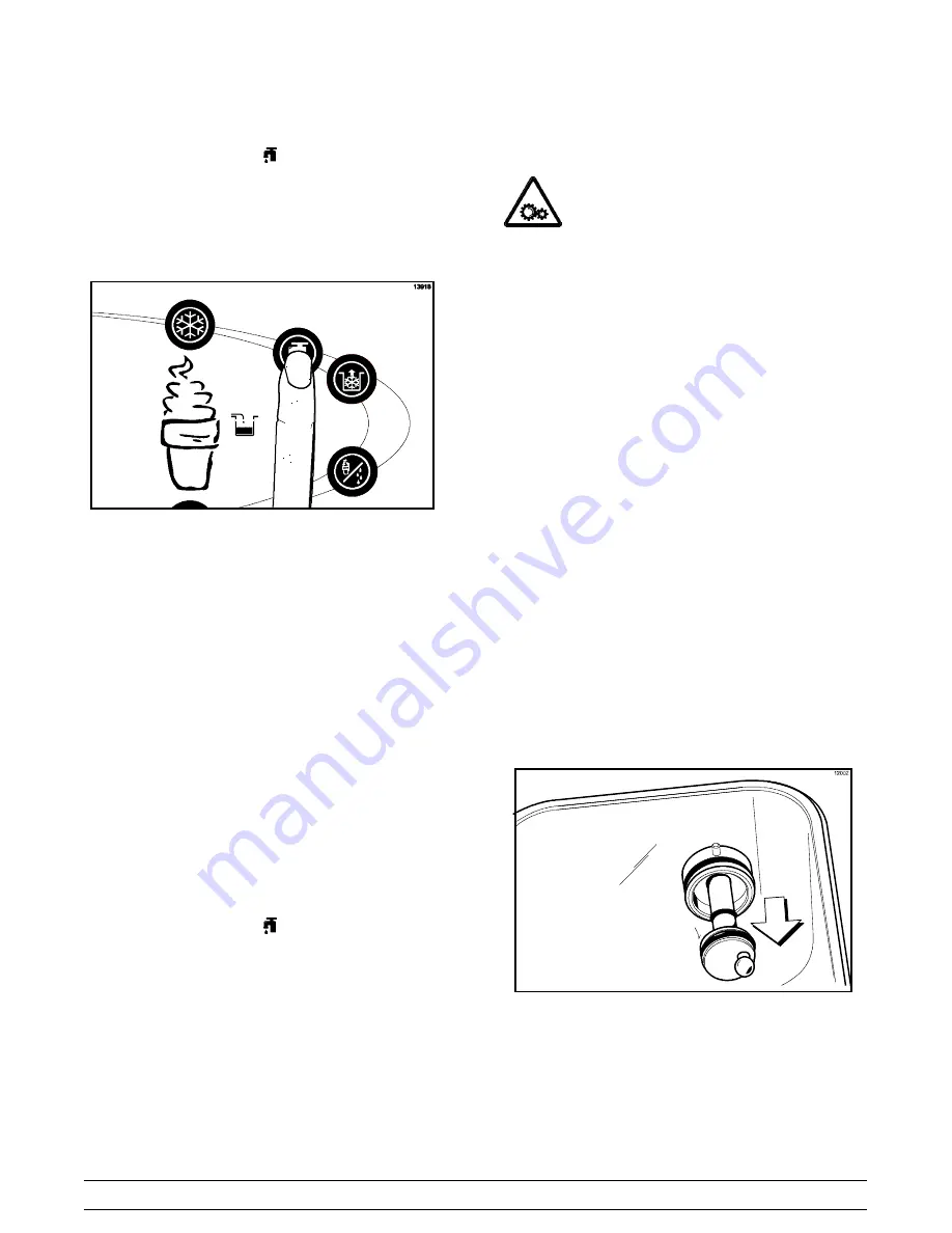
Touch the WASH symbol

. This will cause the

cleaning solution in the freezing cylinder to come in
contact with all areas of the freezing cylinder. Wait
at least 5 minutes before proceeding with these
instructions. (See Figure 67.)

Figure 67

Step 5

Place an empty pail beneath the door spouts.

Step 6

Raise the prime plug.

Step 7

When a steady stream of cleaning solution is flowing
from the prime plug opening in the bottom of the
freezer door, open the draw valve. Draw off all the
solution.

Step 8

Once the cleaning solution stops flowing from the
door spout, close the draw valve and the prime plug.

Step 9

Touch the WASH symbol

, cancelling the Wash

mode.

Repeat these steps on the other side of the
machine.

Disassembly

MAKE SURE THE POWER SWITCH IS IN

THE “OFF” POSITION!

Failure to follow this

instruction may result in severe personal injury from
hazardous moving parts.

Step 1

Remove the handscrews, freezer door, beater and
scraper blades, and drive shaft with drive shaft seal
from the freezing cylinder.

Step 2

Remove the scraper blade clips from the scraper
blades.

Step 3

Remove the drive shaft seal from each drive shaft.

Step 4

From each pump cylinder, remove the retaining pin,
mix inlet adaptor, valve cap, pump gasket, and the
piston. Remove the o-ring from the piston and valve
cap.

Step 5

Remove the freezer door gaskets, front bearings,
pivot pin, draw handles, draw valves, prime plugs,
and design caps. Remove the o-rings from the draw
valves.

Step 6

Remove the pump drive shafts from the drive hubs
in the rear wall of the mix hoppers. (See Figure 68.)

Figure 68

Summary of Contents for C712

Page 1: ...Model C712 Soft Serve Freezer Original Operating Instructions 062179 M 2 03 05 Original Publication Updated 5 20 13 ...

Page 2: ...ound on the data label Model Number Serial Number Electrical Specs Voltage Cycle Phase Maximum Fuse Size A Minimum Wire Ampacity A E February 2005 Taylor All rights reserved 062179 M The word Taylor and the Crown design are registered trademarks in the United States of America and certain other countries Taylor Company 750 N Blackhawk Blvd Rockton IL 61072 ...

Page 3: ...ection 3 Safety 5 Section 4 Operator Parts Identification 7 Model C712 7 Model C712 Door and Beater Assembly 9 X57029 XX Pump A Mix Simplified 10 Accessories 11 Brushes 12 Section 5 Important To the Operator 13 Symbol Definitions 14 Operating Screen Descriptions 15 Manager s Menu 16 Section 6 Operating Procedures 21 Freezing Cylinder Assembly 21 Mix Pump Assembly 26 Sanitizing 28 Priming 30 Manual...

Page 4: ...Section 11 Parts List 41 Wiring Diagrams 50 Note Continuing research results in steady improvements therefore information in this manual is subject to change without notice Note Only instructions originating from the factory or its authorized translation representative s are considered to be the original set of instructions E February 2005 Taylor Original Printing Updated May 2013 All rights reser...

Page 5: ...s must be performed by an authorized Taylor Service Technician This unit has many sharp edges that can cause severe injuries Site Preparation Review the area the unit is to be installed in before uncrating the unit making sure that all possible hazards the user or equipment may come into have been addressed Air Cooled Units The Model C712 air cooled unit requires a minimum of 3 76 mm of clearance ...

Page 6: ...it overcurrent protection or fuse circuit ampacity and other electrical specifications Refer to the wiring diagram provided inside the electrical box for proper power connections CAUTION THIS EQUIPMENT MUST BE PROPERLY GROUNDED FAILURE TO DO SO CAN RESULT IN SEVERE PERSONAL INJURY FROM ELECTRICAL SHOCK DO NOT operate this freezer with larger fuses than specified on the unit data label Failure to f...

Page 7: ...us and must be handled with caution NEVER fill any refrigerant cylinder completely with liquid Filling the cylinder to approximately 80 will allow for normal expansion Use only R134a refrigerant that conforms to the AHI standard 700 specification The use of any other refrigerant may expose users and operators to unexpected safety hazards Refrigerant liquid sprayed onto the skin may cause serious d...

Page 8: ... be collected separately after its use is completed and cannot be disposed as unsorted municipal waste The user is responsible for returning the product to the appropriate collection facility as specified by your local code For additional information regarding applicable local laws please contact the municipal facility and or local distributor Compressor Warranty Disclaimer The refrigeration compr...

Page 9: ...e panel and the equipments frame S DO NOT operate the freezer unless it is properly grounded S DO NOT operate the freezer with larger fuses than specified on the freezer data label S All repairs must be performed by an authorized Taylor service technician The main power supplies to the machine must be disconnected prior to performing any repairs S For Cord Connected Units Only Taylor authorized se...

Page 10: ...actical experience with the appliance in particular as far as safety and hygiene are concerned This freezer must be placed on a level surface Failure to comply may result in personal injury or equipment damage Cleaning and sanitizing schedules are governed by your state or local regulatory agencies and must be followed accordingly Please refer to the cleaning section of this manual for the proper ...

Page 11: ...7 Model C712 Operator Parts Identification 121022 Section 4 Operator Parts Identification Model C712 Figure 1 ...

Page 12: ...CONE 055987 10 FILTER AIR POLY FLO 052779 11 11 PANEL A FILTER LOUVERED X59928 12 CASTER 4 SWV 3 4 10 STEM 044106 13 SCREW 1 4 20 X 3 8 RHM 011694 ITEM DESCRIPTION PART NO 14 PANEL SIDE RIGHT 063087 15 DEFLECTOR BLOWER 047912 16 CASTER 4 SWV 3 4 10 STEM W BRAKE 046437 17 PANEL A FRONT LOWER X59854 SER 18 SHIELD SPLASH WIRE 19 3 4 L 033813 19 TRAY DRIP 19 5 8 L X 4 7 8 033812 20 PAN DRIP 19 1 2 LON...

Page 13: ... GASKET DOOR HT 4 DOUBLE 048926 8 O RING 7 8 OD X 103 W 014402 9 VALVE A DRAW X59843 10 VALVE A DRAW CENTER X62218 11 SEAL DRAW VALVE 034698 ITEM DESCRIPTION PART NO 12 BEARING FRONT SHOE 050348 13 SHOE FRONT HELIX REAR 050346 14 SHOE FRONT HELIX FRONT 050347 15 BEATER A 3 4QT 1 PIN X46231 16 BLADE SCRAPER PLASTIC 046235 17 CLIP SCRAPER BLADE 7 00 046236 18 SHAFT BEATER 032564 19 SEAL DRIVE SHAFT ...

Page 14: ...PTOR MIX INLET 054825 8 O RING 11 16 OD RED 016132 ITEM DESCRIPTION PART NO 9 PIN COTTER 044731 10 SHAFT A DRIVE MIX PUMP HOPPER X41947 10a CRANK DRIVE 039235 10b SHAFT DRIVE 041948 10c O RING DRIVE SHAFT 048632 10d O RING 1 3 4 008904 11 TUBE A FEED LEFT X59808 12 TUBE A FEED RIGHT X59809 13 CLIP RETAINER MIX PUMP 044641 14 RING CHECK 120 OD 056524 NOTE THE STANDARD PUMP X57029 XX IS 14 OVERRUN C...

Page 15: ...O RING REMOVAL 048260 WHT 3 TOOL SHAFT DRIVE PUMP HOPPER 057167 ITEM DESCRIPTION PART NO 4 LUBRICANT TAYLOR 047518 5 SANITIZER STERA SHEEN SEE NOTE KIT A TUNE UP X49463 81 Note A sample container of sanitizer is sent with the unit For reorders order Stera Sheen part no 055492 100 packs or Kay 5 part no 041082 125 packs Not Shown ...

Page 16: ...Figure 5 ITEM DESCRIPTION PART NO 1 BLACK BRISTLE BRUSH 013071 2 DOUBLE END BRUSH 013072 3 WHITE BRISTLE BRUSH 1 x 2 013073 4 BRUSH SET 3 050103 ITEM DESCRIPTION PART NO 5 WHITE BRISTLE BRUSH 3 x 7 023316 6 BRUSH END DOOR SPOUT 039719 7 BRUSH PUMP SPOUT 054068 ...

Page 17: ...ortant To the Operator Figure 6 ITEM DESCRIPTION 1 POWER SWITCH 2 FLUORESCENT DISPLAY 3 KEYPADS 4 MIX OUT INDICATOR 5 STANDBY KEY 6 MIX LOW INDICATOR ITEM DESCRIPTION 7 SELECT KEY 8 SERVICE MENU KEY 9 BRUSH CLEAN COUNTER 10 ARROW KEYS 11 SYRUP TOPPING HEATER KEY ...

Page 18: ... Indicator Lights MIX LOW When the MIX LOW symbol is illuminated the mix hopper has a low supply of mix and should be refilled as soon as possible MIX OUT When the MIX OUT symbol is illuminated the mix hopper has been almost completely exhausted and has an insufficient supply of mix to operate the freezer At this time the AUTO mode is locked out and the freezer will be placed in the STANDBY mode T...

Page 19: ...le This unit features an adjustable draw handle to provide the best portion control giving a better consistent quality to your product and controlling costs The draw handle should be adjusted to provide a flow rate of 5 to 7 1 2 oz 142 to 213 g of product by weight per 10 seconds To INCREASE the flow rate tighten the screw To DECREASE the flow rate loosen the screw See Figure 7 Figure 7 Operating ...

Page 20: ...lay the number of hours since the freezer was last brush cleaned After hour 99 it will change to a letter and a number example A0 A1 B0 B1 etc Manager s Menu The Manager s Menu is used to enter the operator function displays To access the Menu touch the center of the CONE symbol on the control panel The arrow symbols the SEL symbol and the CONE symbol will be lit when the ACCESS CODE screen is dis...

Page 21: ...t the Menu program when the SEL symbol is selected See Figure 14 Figure 14 Menu Options Touch the ARROW symbols to move up or down through the Menu Select a Menu option by touching the SEL symbol Exit the Menu program by selecting EXIT FROM MENU or touch the CONE symbol The following menu options are listed in the Manager s Menu EXIT FROM MENU RESET DRAW COUNTER SET CLOCK AUTO START TIME STANDBY M...

Page 22: ...re 18 SET CLOCK 12 01 7 15 2004 Change Exit Figure 18 Change the time by touching the UP arrow with the cursor under the hour position Move the cursor to the minutes by touching the SEL symbol Once the correct minutes are entered touch the SEL symbol to advance the cursor to the month See Figure 19 SET CLOCK 12 01 7 15 2004 Exit Figure 19 Enter the correct month day and year Then touch the SEL sym...

Page 23: ...h the SEL symbol to activate Standby Discontinue Standby operation by exiting the Manager s Menu and select the AUTO mode See Figure 24 STANDBY MODE EXIT Figure 24 The MIX LEVEL AUDIBLE option when enabled will alert the operator with an audible tone when there is mix low or mix out condition The following screen is displayed upon selecting this option See Figure 25 MIX LEVEL AUDIBLE Enable Disabl...

Page 24: ...erature in the freezing cylinder was above 41_F 5_C more than four hours HPR 41F 5C AFTER PF The mix temperature in the hopper was above 41_F 5_C more than four hours following a power failure BRL 41F 5C AFTER PF The mix temperature in the freezing cylinder was above 41_F 5_C more than four hours following a power failure HPR 45F 7C AFTER 1 HR The mix temperature in the hopper was above 45_F 7_C m...

Page 25: ...y result in severe personal injury from hazardous moving parts Step 1 Before installing the beater drive shaft lubricate the groove on the beater drive shaft Step 2 Slide the beater drive shaft boot seal over the small end of the beater drive shaft and engage into the groove on the shaft Step 3 Heavily lubricate the inside portion of the boot seal and also lubricate the flat end of the boot seal t...

Page 26: ...aper blade must fit securely over the pin to prevent costly damage Step 7 Holding the rear blade on the beater slide it into the freezing cylinder halfway Install the front scraper blade over the front holding pin See Figure 34 Figure 34 Step 8 Install the beater shoes See Figure 35 Figure 35 Step 9 Slide the beater assembly the rest of the way into the freezing cylinder Make sure the beater assem...

Page 27: ...grooves on each prime plug Apply an even coat of Taylor Lube to the o rings and shafts Figure 38 Step 11 Insert the prime plugs into the holes in the top of the freezer door and push down Figure 39 Step 12 To install the freezer door insert the baffle rods through the beaters in the freezing cylinders Figure 40 With the door seated on the freezer studs install the handscrews Use the long handscrew...

Page 28: ...the H ring and o rings Figure 41 Step 14 Lubricate the inside of the freezer door spouts top and bottom Figure 42 Step 15 Insert the draw valves from the bottom until the slot in each draw valve comes into view Figure 43 Step 16 Position each draw handle with the adjustment screw facing down Slide the fork of each draw handle into the slot of each draw valve starting from the right Figure 44 ...

Page 29: ...r product and controlling costs The draw handle should be adjusted to provide a flow rate of 5 to 7 1 2 oz 142 g to 213 g of product by weight per 10 seconds To INCREASE the flow rate tighten the screw To DECREASE the flow rate loosen the screw Figure 46 Step 18 Snap the design caps over the bottom of the door spouts Figure 47 Step 19 Slide the two rear drip pans into the holes in the back panel S...

Page 30: ...es in the material are present Replace any defective parts immediately and discard the old Step 2 Assemble the piston Slide the red o ring into the groove of the piston DO NOT lubricate the o ring See Figure 50 Figure 50 Step 3 Apply a thin layer of lubricant to the inside of the pump cylinder at the retaining pin hole end See Figure 51 Figure 51 Step 4 Insert the piston into the retaining pin hol...

Page 31: ...the pump cylinder See Figure 56 Figure 56 The adapter must be positioned into the notch located at the end of the pump cylinder Step 9 Secure the pump parts in position by sliding the retaining pin through the cross holes located at one end of the pump cylinder See Figure 57 Figure 57 Note The head of the retaining pin should be located at the top of the pump when installed Step 10 Assemble the fe...

Page 32: ...Figure 60 Figure 60 Step 14 Install the hex end of the drive shaft into the drive hub at the rear wall of the mix hopper See Figure 61 Figure 61 Note For ease in installing the pump position the ball crank of the drive shaft in the 3 o clock position Repeat these steps for the other side of the machine Sanitizing Step 1 Prepare a pail of approved 100 PPM sanitizing solu tion examples 2 1 2 gal 9 5...

Page 33: ...mp clip over the collar of the pump making sure the clip fits into the grooves in the collar See Figure 63 Figure 63 Step 5 Install the pump end of the mix feed tube and secure with the cotter pin Failure to follow this instruction could result in sanitizer spraying on the operator See Figure 64 Figure 64 Step 6 Prepare another pail of approved 100 PPM sanitiz ing solution examples 2 1 2 gal 9 5 l...

Page 34: ...nder remove the cotter pin from the outlet fitting of the mix pump Insert the outlet end of the mix feed tube into the mix inlet hole in the mix hopper Place the inlet end of the mix feed tube into the outlet fitting of the mix pump Secure with cotter pin Step 5 Select the AUTO symbol Note The brush clean counter will start at this time Step 6 Fill the hopper with fresh mix and place the mix hoppe...

Page 35: ...ter from the door spout Close the draw valve and push the prime plug down Step 4 Touch the WASH symbol cancelling the Wash mode Step 5 Repeat this procedure using clean warm water until the water being discharged is clear Repeat these steps for the other side of the machine Hopper Cleaning Step 1 Prepare a pail of approved 100 PPM cleaning solu tion examples 2 1 2 gal 9 5 liters of Kay 5R or 2 gal...

Page 36: ...t these steps on the other side of the machine Disassembly MAKE SURE THE POWER SWITCH IS IN THE OFF POSITION Failure to follow this instruction may result in severe personal injury from hazardous moving parts Step 1 Remove the handscrews freezer door beater and scraper blades and drive shaft with drive shaft seal from the freezing cylinder Step 2 Remove the scraper blade clips from the scraper bla...

Page 37: ... with the freezer are available for brush cleaning Step 2 Thoroughly brush clean all disassembled parts in the cleaning solution making sure all lubricant and mix film is removed Be sure to brush all surfaces and holes especially the holes in the pump components and the draw valve holes in the freezer door Rinse all parts with clean warm water Place the parts on a clean dry surface to air dry over...

Page 38: ...e job of cleaning or sanitizing j 6 The temperature of mix in the mix hopper and walk in cooler should be below 40_F 4 4_C j 7 Discard remaining mix from the freezer during Cleaning Procedures Regular Maintenance Checks j 1 Replace scraper blades that are nicked or damaged Before installing the beater assembly be certain that scraper blades are properly attached to the helix j 2 Check the rear she...

Page 39: ...n the condenser This is extremely important Failure to follow this procedure may cause severe and costly damage to the refrigeration system Your local Taylor Distributor can perform this winter storage service for you Wrap detachable parts of the freezer such as beater blades drive shaft and freezer door and place them in a protected dry place Rubber trim parts and gaskets can be protected by wrap...

Page 40: ...e machine off Press the reset button Restart the machine in AUTO e The pump motor is not running in the AUTO mode e Push the pump reset button Check pump motor is operating when the draw valve is raised 15 f Freeze up in mix inlet hole f Call an authorized service technician g The mix pump ball crank is broken g Call an authorized service technician h Feed tube or check ring not properly installed...

Page 41: ...chnician 6 Mix Low and Mix Out probes are not functioning a Milkstone build up in the hopper a Clean hoppers thoroughly 33 7 Product is collecting on top of the freezer door a The top o ring on draw valve is improperly lubricated or worn a Lubricate properly or replace the o ring 24 8 Excessive mix leakage from the bottom of door spout a Bottom o ring on draw valve is improperly lubricated or worn...

Page 42: ...freezer door baffle rod b Replace freezer door 23 c Broken beater pins c Replace beater assembly 22 d Beater assembly is bent d Replace beater assembly 22 e Gear box is out of alignment e Call an authorized service technician 12 The product makes a popping sound when drawn a Draw rate is set too fast a Adjust draw rate of 5 to 7 1 2 oz 142 g to 213 g of product by weight in 10 seconds 25 b Pump as...

Page 43: ...ve O Ring X Mix Feed Tube O Ring X Pump O Ring X Prime Plug O Ring X Pump Valve Gasket X Mix Feed Tube Check Ring X Pump Drive Shaft O Ring X White Bristle Brush 3 x 7 Inspect Replace if Necessary Minimum White Bristle Brush 3 x 1 2 Inspect Replace if Necessary Minimum Black Bristle Brush 1 x 2 Inspect Replace if Necessary Minimum Double Ended Brush Inspect Replace if Necessary Minimum Brush Set 3...

Page 44: ...iginal date of unit installation with a replacement parts warranty of twelve months Class 000 Parts Class 000 parts are considered wear items no warranty Class Parts See warranty explanation on the back of the check out card CAUTION Warranty is valid only if the parts are authorized Taylor parts purchased from an authorized Taylor Distributor and the required service work is provided by an authori...

Page 45: ...RASS BEARING 028991 2 000 GUIDE DRIP SEAL 028992 2 000 WASHER BEARING LOCK 012864 2 000 BEATER A 3 4QT 1 PIN SUPPORT X46231 2 103 BLADE SCRAPER PLASTIC 8 1 8L 046235 4 000 CLIP SCRAPER BLADE 7 00 INCH 046236 4 103 BELT AX32 032769 4 000 BELT AX33 024396 4 000 220 240V 50HZ 1PH BLOWER A X53725 27 1 103 CAPACITOR RUN 7 5UF 370V 034749 1 103 CLIP SCREEN BLOWER 053730 4 103 MOTOR FAN 208 230V 50 60 HZ...

Page 46: ...60UF 220 275V 047703 1 103 AUX KIT MOUNTING COMPRESSOR 047704 1 000 AUX COMPRESSOR CS20K6E PFV 238 057011 27 2 512 208 230V 60HZ 1PH S N K7072861 BLOCK TERMINAL 2P L1 L2 039422 2 103 CAPACITOR START 189 227UF 33 033044 1 2 103 CAPACITOR RUN 40MF 440V 036049 2 103 RELAY START COMPRESSOR 052401 27 2 103 COMPRESSOR CS20K6E TF5 23 057011 33 2 512 208 230V 60HZ 3PH COMPRESSOR CS20K6E PFZ 238 057011 40 ...

Page 47: ...RAM WIRING C712 059898 40 1 000 220 240V 50HZ 1PH DIAGRAM WIRING C712 059898 58 1 000 380 415V 50HZ 3N DOOR A 3SPT LG BAF W PRG C712 X59921 SER 1 103 BEARING FRONT SHOE 050348 2 000 DECAL DOOR 3 SPOUT TWIN TWIST 062239 1 NNN GASKET DOOR 4 DART 048926 1 2 000 HANDLE A DRAW C602 X56421 1 3 103 SCREW ADJUSTMENT 5 16 24 602 056332 3 103 O RING 1 4 OD X 070W 50 DURO 015872 3 000 PIN HANDLE TWIN C712 C7...

Page 48: ...230V 60HZ 3PH HARNESS WIRE COMPRESSOR 062056 33G 2 103 208 230V 60HZ 3PH HARNESS WIRE BEATER MTR 3 PH 062053 33G 2 103 380 415V 50HZ 3N HARNESS WIRE COMPRESSOR 062056 33G 2 103 380 415V 50HZ 3N HARNESS WIRE BLOWER C712 C713 062057 1 103 HARNESS WIRE LW V CNTL CHNNL 062049 1 103 HARNESS WIRE LW V MIX HOPPER 062050 1 103 HARNESS WIRE POWER SWITCH 062051 1 103 HARNESS WIRE MIX PMP C712 C716 062055 2 ...

Page 49: ...OZ 047518 1 000 MANIFOLD 1 2S THRU 1 4S OUT 2 046687 2 NNN LINE DISCHARGE MAN OPER C712 062179 M 1 000 MOTOR 1 5 HP CAPS 10 2 O CLOCK 021522 27 2 212 208 230V 60HZ 1PH MOTOR 1 5 HP 021522 33 2 212 208 230V 60HZ 3PH MOTOR 1 5 HP CAPS 10 2 O CLOCK 021522 34 2 212 220 240V 50HZ 1PH MOTOR 1 5 HP 021522 35 2 212 380 415V 50HZ 3N MOTOR FAN 062253 27 1 103 AUX MOTOR REDUCER 32 RPM HPR PUMPM 036955 34 2 2...

Page 50: ...HIP SOFTWARE C602 FP X40821 1 103 PIN COTTER HAIRPIN 1 8DIA 044731 2 103 PLATE DEC C712 SYRUP RAIL 062121 1 103 PROBE A MIX X56912 2 103 MIX LEVEL SPACER PROBE MIX MIDDLE 056907 2 000 SPACER PROBE MIX UPPER 056910 2 000 PROBE THERMISTOR BARREL 2 TOL 038061 BLK 8 103 066644 CONTROL HARNESS 20 PROBE W 90 LEADS PULLEY 2AK22 X 625 6265 016403 2 103 208 230V 60HZ 1PH 208 230V 60HZ 3PH PULLEY 2AK27 X 62...

Page 51: ...IM SCREW 5 16 18X3 1 4STL HEXCAP 022678 4 000 SCREW 5 16 18X2 3 4 HEX CAP 004191 8 000 SHAFT A DRIVE MIX PUMP HOPPER X41947 2 103 CRANK DRIVE HOPPER MIX PUMP 039235 2 103 O RING 1 2 ID X 139W 048632 4 000 O RING 1 3 4 OD X 139W 008904 2 000 SHAFT DRIVE MIX PUMP HOPPER 041948 2 103 SEAL DRIVE SHAFT 032560 2 000 SHIELD SPLASH WIRE 19 3 4 L 033813 1 103 SHELL A INSULATED C712 X63324 SER 1 512 STUD NO...

Page 52: ... 103 O RING 11 16ODX 103W RED 016132 4 000 PUMP TUBES TUBE A FEED RIGHT C712 C717 X59809 1 103 O RING 11 16ODX 103W RED 016132 4 000 PUMP TUBES TUBE A FEED SS 5 32 HOLE DIA X29429 2 2 103 O RING 643 OD X 077W 018572 8 000 VALVE ACCESS 1 4 MFLX1 4 S 90 047016 1 103 DANFOSS ACCESS VALVE ACCESS 1 4FL X 1 4SOLDER 044404 1 103 LINE SUCTION DNFS VALVE ACCESS 1 4MFL X 3 8ODSDR 053565 4 103 LINE DISCHARGE...

Page 53: ...47912 1 103 GUARD BLOWER 022505 1 103 HOSE RUBBER 1 2 ID X 7 8 OD R50200 15 000 OUTLET A TEE X25900 1 103 PANEL SIDE L W C C712 C717 062160 1 103 PANEL SIDE R W C C712 C717 062161 1 103 PLATE CONDENSER W C 062043 1 103 TEE 3 8 PIPE WATER VALVE 032953 1 103 VALVE WATER 3 8 REG HEAD PRESS 046686 2 103 ...

Page 54: ...Model C712 059898 27 5 13 ...

Page 55: ...Model C712 059898 33 5 13 ...

Page 56: ...Model C712 059898 40 5 13 ...

Page 57: ...Model C712 059898 58 5 13 ...

Reviews: