C713 Operator Training
C713 Operator Training
C713 Operator Training
C713 Operator Training
13
Freezing Cylinder Assembly
Step 10
To assemble the freezer door, place the door gaskets into the grooves on the back of the freezer
door. Slide the front bearings over the baffle rods. The flanged edges should be against the door. DO
NOT lubricate the gaskets or bearings.
Step 11
Slide the two o-rings into the grooves on each prime plug. Apply an even coat of Taylor Lube to the
o-rings and shafts.
Step 12
Insert the prime plugs into the holes in the top of the freezer door and push down.
Step 13
To install the freezer door, insert the baffle rods through the beaters in the freezing cylinders.
With the door seated on the freezer studs, install the handscrews. Use the long handscrews on the
top and the short handscrews on the bottom. Tighten them equally in a criss-cross pattern to insure
the door is snug.
Step 14
Slide the three o-rings into the grooves of each standard draw valve. Slide the H-ring and o-ring into
the grooves of the center draw valve. Lubricate the H-ring and o-rings.
Step 15
Lubricate the inside of the freezer door spouts, top and bottom.
Step 16
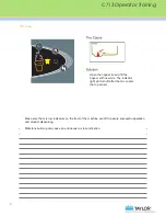
Insert the draw valves from the bottom until the slot in the draw valves come into view.
Step 17
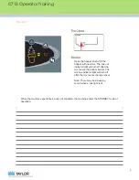
Slide the fork of the draw handles in the slot of the draw valves, starting from the right. Slide the
pivot pin through each draw handle as they are inserted into the draw valves.
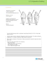
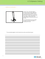
Note: This freezer features three adjustable draw handles to provide portion control, giving a better
consistent quality to your product and controlling costs. The draw handle should be adjusted to pro-
vide a flow rate of 5 to 7-1/2 oz. (142 g. to 213 g.) of product by weight per 10 seconds.
To INCREASE the flow rate, turn the adjustment screw CLOCKWISE. Turn the adjustment screw
COUNTER-CLOCKWISE to DECREASE the flow rate.

