background image

32

Model C713

Important: Operator Checklist

j

4. Dispose of o-rings and seals if they are worn,

torn, or fit too loosely, and replace with new
ones.

j

5. Follow all lubricating procedures as outlined in

“Assembly”.

j

6. If your machine is air cooled, check the

condensers for accumulation of dirt and lint.
Dirty condensers will reduce the efficiency
and capacity of the machine. Condensers
should be cleaned

monthly

with a soft brush.

Never

use screwdrivers or other metal probes

to clean between the fins.

Note:

For machines equipped with an air

filter, it will be necessary to vacuum clean the
filters on a monthly schedule.

Caution: Always disconnect

electrical power prior to cleaning the
condenser.

Failure to follow this instruction

may result in electrocution.

j

7. If your machine is water cooled, check the

water lines for kinks or leaks. Kinks can occur
when the machine is moved back and forth for
cleaning or maintenance purposes.
Deteriorated or cracked water lines should be
replaced only by an authorized Taylor
distributor.

Winter Storage

If the place of business is to be closed during the
winter months, it is important to protect the freezer
by following certain precautions, particularly if the
building is subject to freezing conditions.

Disconnect the freezer from the main power source
to prevent possible electrical damage.

On water cooled freezers, disconnect the water
supply. Relieve pressure on the spring in the water
valve. Use air pressure on the outlet side to blow out
any water remaining in the condenser.

This is

extremely important.

Failure to follow this

procedure may cause severe and costly damage to
the refrigeration system.

Your local Taylor Distributor can perform this winter
storage service for you.

Wrap detachable parts of the freezer such as
beater, blades, drive shaft, and freezer door, and
place them in a protected dry place. Rubber trim
parts and gaskets can be protected by wrapping
them with moisture-proof paper. All parts should be
thoroughly cleaned of dried mix or lubrication which
attract mice and other vermin.

It is recommended that an authorized service
technician perform winter storage draining, to insure
all water has been removed. This will guard against
freezing and rupturing of the components.

Summary of Contents for c713

Page 1: ...Model C713 Soft Serve Freezer Original Operating Instructions 062180 M 2 11 05 Original Publication Updated 2 10 12 ...

Page 2: ...n the data label Model Number Serial Number Electrical Specs Voltage Cycle Phase Maximum Fuse Size A Minimum Wire Ampacity A E February 2005 Taylor All rights reserved 062180 M The word Taylor and the Crown design are registered trademarks in the United States of America and certain other countries Taylor Company 750 N Blackhawk Blvd Rockton IL 61072 ...

Page 3: ...tions 2 Beater Rotation 3 Refrigerant 3 Section 2 To the Operator 4 Section 3 Safety 5 Section 4 Operator Parts Identification 7 Model C713 7 Door and Beater Assembly 9 Accessories 10 Brushes 11 Section 5 Important To the Operator 12 Symbol Definitions 13 Operating Screen Descriptions 15 Manager s Menu 16 Section 6 Operating Procedures 21 Freezing Cylinder Assembly 21 Sanitizing 26 Priming 27 ...

Page 4: ...t Schedule 36 Section 10 Parts List 37 Wiring Diagrams 45 Note Continuing research results in steady improvements therefore information in this manual is subject to change without notice Note Only instructions originating from the factory or its authorized translation representative s are considered to be the original set of instructions E February 2005 Taylor Original Publication Updated February...

Page 5: ...ust be performed by an authorized Taylor Service Technician This unit has many sharp edges that can cause severe injuries Site Preparation Review the area the unit is to be installed in before uncrating the unit making sure that all possible hazards the user or equipment may come into have been addressed Air Cooled Units The Model C713 air cooled unit requires a minimum of 3 76 mm of clearance on ...

Page 6: ...el on the unit Check the data label s on the freezer for branch circuit overcurrent protection or fuse circuit ampacity and other electrical specifications Refer to the wiring diagram provided inside of the electrical box for proper power connections CAUTION THIS EQUIPMENT MUST BE PROPERLY GROUNDED FAILURE TO DO SO CAN RESULT IN SEVERE PERSONAL INJURY FROM ELECTRICAL SHOCK DO NOT operate this free...

Page 7: ...ting Potential ODP of zero 0 However any gas under pressure is potentially hazardous and must be handled with caution NEVER fill any refrigerant cylinder completely with liquid Filling the cylinder to approximately 80 will allow for normal expansion Refrigerant liquid sprayed onto the skin may cause serious damage to tissue Keep eyes and skin protected If refrigerant burns should occur flush immed...

Page 8: ... be collected separately after its use is completed and cannot be disposed as unsorted municipal waste The user is responsible for returning the product to the appropriate collection facility as specified by your local code For additional information regarding applicable local laws please contact the municipal facility and or local distributor Compressor Warranty Disclaimer The refrigeration compr...

Page 9: ...both the removable panel and the equipments frame DO NOT use a water jet to clean or rinse the freezer Failure to follow these instructions may result in serious electrical shock S DO NOT operate the freezer unless it is properly grounded S DO NOT operate the freezer with larger fuses than specified on the freezer data label S All repairs must be performed by an authorized Taylor service technicia...

Page 10: ... the mounting holes must NOT be used to lift or hold the dispenser Failure to follow this instruction can result in personal injury to fingers or equipment damage Cleaning and sanitizing schedules are governed by your state or local regulatory agencies and must be followed accordingly Please refer to the cleaning section of this manual for the proper procedure to clean this unit DO NOT obstruct ai...

Page 11: ...7 Model C713 Operator Parts Identification 111115 Section 4 Operator Parts Identification Model C713 Figure 1 ...

Page 12: ...EL A FRONT X63879 10 PANEL A FRONT X59836 11 STUD NOSE CONE 055987 12 FILTER AIR POLY FLO 052779 11 13 PANEL A FILTER LOUVERED X59928 ITEM DESCRIPTION PART NO 14 CASTER 4 SWV 3 4 10 STEM 044106 15 SCREW 1 4 20 X 3 8 RHM SS 011694 16 PANEL CORNER FRONT RIGHT 063087 17 CASTER 4 SWV 3 4 10 STEM W BRAKE 046437 18 DEFLECTOR BLOWER 047912 19 SHIELD SPLASH WIRE 19 3 4 L 033813 20 PANEL A FRONT LOWER X598...

Page 13: ...6 NUT STUD BLACK 3 250 LONG 058765 7 NUT STUD BLACK 2 563 LONG 058764 8 DOOR A 3SPT LG BAF W PRG X59922 9 VALVE A DRAW X59843 10 VALVE A DRAW CENTER X62218 ITEM DESCRIPTION PART NO 11 CAP DESIGN 1 010 ID 6 PT 014218 12 SEAL DRAW VALVE 034698 13 O RING 7 8 OD X 103 W 014402 14 PIN HANDLE TWIN 059894 15 GASKET DOOR HT 4 DOUBLE 048926 16 BEARING FRONT 050216 17 BLADE SCRAPER PLASTIC 17L 035174 18 BEA...

Page 14: ...LOR 047518 2 TOOL O RING REMOVAL 048260 WHT 3 PAIL MIX 10 QT 013163 ITEM DESCRIPTION PART NO 4 SANITIZER STERA SHEEN SEE NOTE KIT A TUNE UP X49463 80 Not Shown Note A sample container of sanitizer is sent with the unit For reorders order Stera Sheen part no 055492 100 2 oz packs or Kay 5 part no 041082 200 packs ...

Page 15: ... 4 ITEM DESCRIPTION PART NO 1 BLACK BRISTLE BRUSH 013071 2 DOUBLE END BRUSH 013072 3 WHITE BRISTLE BRUSH 1 x 2 013073 4 WHITE BRISTLE BRUSH 3 x 7 023316 ITEM DESCRIPTION PART NO 5 BRUSH END DOOR SPOUT SS 039719 6 BRUSH SET LVB 050103 7 BRUSH PUMP SPOUT 054068 ...

Page 16: ...ion 5 Important To the Operator Figure 5 ITEM DESCRIPTION 1 POWER SWITCH 2 LIQUID CRYSTAL DISPLAY 3 KEYPADS 4 MIX OUT INDICATOR 5 STANDBY KEY ITEM DESCRIPTION 6 MIX LOW INDICATOR 7 SELECT KEY 8 SERVICE MENU KEY 9 BRUSH CLEAN COUNTER 10 ARROW KEYS ...

Page 17: ...ossible MIX OUT When the MIX OUT symbol is illuminated the mix hopper has been almost completely exhausted and has an insufficient supply of mix to operate the freezer At this time the AUTO mode is locked out and the freezer will be placed in the STANDBY mode To initiate the refrigeration system add mix to the mix hopper and touch the AUTO symbol The freezer will automatically begin operation Stan...

Page 18: ...O symbol to resume normal operation If the freezer shuts down again contact your authorized service technician Feed Tube Figure 6 The feed tube serves two purposes One end of the tube has a hole and the other end does not 1 Normal Operation During normal operation the end of the feed tube with the hole is placed into the mix inlet hole Every time the draw handle is raised new mix and air from the ...

Page 19: ...ANGUAGE SYSTEM DATA CONFIG DATA and LOCKOUT DATA During the INITIALIZING LANGUAGE screen the alarm will be on If the system detects corrupt data during INITIALIZING the following display will alert the operator that the control settings may have been changed See Figure 8 NVRAM FAULT RESET TO DEFAULTS PRESS SEL KEY Figure 8 See NVRAM FAULT for instructions if the above message appears on the screen...

Page 20: ...d is used to scroll downward in text displays SEL advances the cursor position to the right and is used to select menu options Note The machine will continue operation in the mode it was in when the menu was selected However the control keys will not be lit and are non functional when the Manager s Menu is displayed Entering Access Code With the ACCESS CODE screen on the display use the SEL symbol...

Page 21: ...Figure 15 Reset the SERVING COUNTER by selecting the SEL symbol to advance to the next screen Select the UP arrow symbol to move the arrow to YES and select the SEL symbol The servings counter will reset to zero and exit back to the Manager s Menu See Figure 16 RESET DRAW COUNTER YES NO Figure 16 The SET CLOCK option allows the Manager to adjust the control clock date and time The date and time ma...

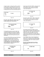
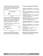
Page 22: ...O START TIME can also be disabled and require starting the AUTO mode manually See Figure 21 AUTO START TIME DISABLED Enable Disable Figure 21 Enable the AUTO START TIME by selecting the UP arrow symbol to move the arrow up to Enable Touch the SEL symbol to advance to the next screen See Figure 22 AUTO START TIME 00 00 Change Exit Figure 22 Program the AUTO START TIME by selecting the UP arrow symb...

Page 23: ...st indicates the variable messages that may appear Faults Occurring While in AUTO Mode HPR 41F 5C AFTER 4 HR The mix temperature in the hopper was above 41_F 5_C more than four hours BRL 41F 5C AFTER 4 HR The mix temperature in the freezing cylinder was above 41_F 5_C more than four hours HPR 41F 5C AFTER PF The mix temperature in the hopper was above 41_F 5_C more than four hours following a powe...

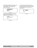
Page 24: ...1 04 Next Figure 27 Touch the SEL symbol to advance to the next system information screen containing the software language version See Figure 28 Language V1 11 r 00 English 515 Next Figure 28 Touch the SEL symbol to advance to the third system information screen containing the model bill of material and machine serial number Touching the SEL symbol again will return to the Menu list See Figure 29 ...

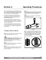
Page 25: ...er Assembly Note When lubricating parts use an approved food grade lubricant example Taylor Lube MAKE SURE THE POWER SWITCH IS IN THE OFF POSITION Failure to follow this instruction may result in severe personal injury from hazardous moving parts Step 1 Before installing the beater drive shaft lubricate the groove on the beater drive shaft Step 2 Slide the beater drive shaft boot seal over the sma...

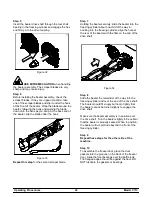
Page 26: ...e beater into the freezing cylinder about one third of the way in Looking into the freezing cylinder align the hole at the rear of the beater with the flats on the end of the drive shaft Figure 34 Step 8 Slide the beater the remainder of the way into the freezing cylinder and over the end of the drive shaft The beater should fit snugly but not so tightly that the beater cannot be turned slightly t...

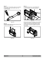
Page 27: ...nto the holes in the top of the freezer door and push down Figure 36 Step 13 To install the freezer door insert the baffle rods through the beaters in the freezing cylinders Figure 37 With the door seated on the freezer studs install the handscrews Use the long handscrews on the top and the short handscrews on the bottom Tighten them equally in a criss cross pattern to insure the door is snug Figu...

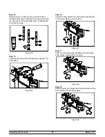
Page 28: ...ngs Figure 39 Step 15 Lubricate the inside of the freezer door spouts top and bottom Figure 40 Step 16 Insert the draw valves from the bottom until the slot in the draw valves come into view Figure 41 Step 17 Slide the fork of the draw handles in the slot of the draw valves starting from the right Figure 42 Step 18 Slide the pivot pin through each draw handle as they are inserted into the draw val...

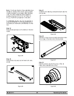
Page 29: ... adjustment screw CLOCKWISE Turn the adjustment screw COUNTER CLOCKWISE to DECREASE the flow rate Step 19 Snap the design caps over the bottom of the door spouts Figure 44 Step 20 Slide the two drip pans into the holes in the side panels Figure 45 Step 21 Install the front drip tray and splash shield under the door spouts Figure 46 Step 22 Slide two o rings on one end of the feed tube Slide two o ...

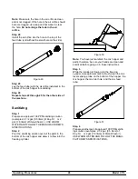
Page 30: ...liters of Kay 5R or 2 gal 7 6 liters of Stera SheenR USE WARM WATER AND FOLLOW THE MANUFACTURER S SPECIFICATIONS Step 2 Pour the sanitizing solution over all the parts in the bottom of the mix hopper and allow it to flow into the freezing cylinder Figure 50 Note You have just sanitized the mix hopper and parts therefore be sure your hands are clean and sanitized before going on in these instructio...

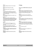
Page 31: ...Step 12 Lubricate the feed tube o rings on the end with the small hole on the side Stand the feed tube in the corner of the hopper Step 13 Repeat these steps for the other side of the machine Priming Note Use only FRESH MIX when priming the freezer Step 1 Place an empty mix pail beneath the door spouts With the prime plug in the UP position pour 2 1 2 gallons 9 5 liters of FRESH mix into the mix h...

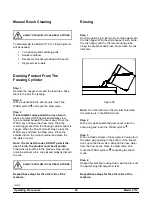
Page 32: ...cooler Note If local health codes DO NOT permit the use of rerun the product must be discarded Follow the instructions in the previous step except drain the product into a mix pail and properly discard the mix ALWAYS FOLLOW LOCAL HEALTH CODES Repeat these steps for the other side of the machine Rinsing Step 1 Pour two gallons 7 6 liters of cool clean water into the mix hopper With the white hopper...

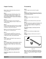
Page 33: ...lution is flowing from the prime plug opening in the bottom of the freezer door open the draw valve Draw off all the solution Step 7 Once the cleaning solution stops flowing from the door spout close the draw valve and touch the WASH symbol cancelling the Wash mode Repeat these steps on the other side of the machine Disassembly Step 1 Place the power switch in the OFF position Step 2 Remove the ha...

Page 34: ...d parts in the cleaning solution making sure all lubricant and mix film is removed Be sure to brush all surfaces and holes especially the holes in the freezer door Step 3 Rinse all parts with clean warm water Place the parts on a clean dry surface to air dry overnight Step 4 Return to the freezer with a small amount of cleaning solution Using the black brush clean the rear shell bearing at the bac...

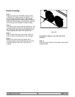
Page 35: ...IF LOCAL HEALTH CODES PERMIT THE USE OF RERUN make sure the mix rerun is stored in a sanitized covered NSF approved stainless steel rerun container and used the following day DO NOT prime the machine with rerun When using rerun skim off the foam and discard then mix the rerun with fresh mix in a ratio of 50 50 during the day s operation j 6 On a designated day of the week run the mix as low as fea...

Page 36: ...butor Winter Storage If the place of business is to be closed during the winter months it is important to protect the freezer by following certain precautions particularly if the building is subject to freezing conditions Disconnect the freezer from the main power source to prevent possible electrical damage On water cooled freezers disconnect the water supply Relieve pressure on the spring in the...

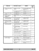
Page 37: ...RLOAD message displayed d Turn the machine off Press the reset button Restart the machine in AUTO e Freeze up in mix inlet hole e Call an authorized service technician f Feed tube is not properly installed f Make sure feed tube is properly installed 27 2 The product is too soft a Draw rate is set too fast a Adjust draw rate of 5 to 7 1 2 oz 142 g to 213 g of product by weight in 10 seconds 25 3 Th...

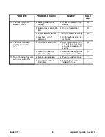
Page 38: ... a Bottom o ring on draw valve is improperly lubricated or worn a Lubricate properly or replace the o ring 24 9 Excessive mix leakage into the long drip pan a The seal on drive shaft is improperly lubricated or worn a Lubricate properly or replace the seal 21 b The seal is installed inside out on the drive shaft b Install correctly 21 c Inadequate lubrication of the drive shaft c Lubricate properl...

Page 39: ...d Gear box is out of alignment d Call an authorized service technician 12 The product makes a popping sound when drawn a Draw rate is set too fast a Adjust draw rate of 5 to 7 1 2 oz 142 g to 213 g of product by weight in 10 seconds 25 b Freezing cylinder not primed correctly b Drain the freezing cylinder and reprime the machine 27 13 No control panel functions with power switch ON a Machine is un...

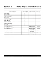
Page 40: ...ezer Door Gasket X Front Bearing X Draw Valve O Ring X Draw Valve Seal X Prime Plug O Ring X Mix Feed Tube O Ring X Design Cap X White Bristle Brush 3 x 7 Inspect Replace if Necessary Minimum White Bristle Brush 1 x 2 Inspect Replace if Necessary Minimum Black Bristle Brush 1 x 2 Inspect Replace if Necessary Minimum Double Ended Brush Inspect Replace if Necessary Minimum ...

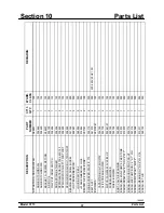
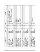
Page 41: ...T BRASS BEARING 028991 2 000 GUIDE DRIP SEAL 028992 2 000 WASHER BEARING LOCK 012864 2 000 BEATER A 3 4QT HELICORE X31761 2 103 BLADE SCRAPER PLASTIC 17L 035174 4 000 BELT AX31 041575 4 000 220 240V 50HZ 1PH BLOWER A X53725 27 1 103 CAPACITOR RUN 7 5UF 370V 034749 1 103 CLIP SCREEN BLOWER 053730 4 103 MOTOR FAN 208 230V 50 60 HZ 053481 27 1 103 SCREEN BLOWER 053729 1 103 WHEEL BLOWER 053726 1 103 ...

Page 42: ...5UF 440V 048132 2 103 CAPACITOR START 189 227UF 250V 053106 2 103 RELAY START COMPRESSOR 051957 27 2 103 COMPRESSOR CS18K6E TF5 238 052397 33 2 512 208 230V 60HZ 3PH COMPRESSOR CS18K6E PFJ 238 052397 40 2 512 220 240V 50HZ 1PH BLOCK TERMINAL 2P L1 N 039421 2 103 CAPACITOR START 145 175UF 25 052399 2 103 CAPACITOR RUN 45UF 370V 052400 2 103 RELAY START COMPRESSOR 052401 27 2 103 COMPRESSOR CS18K6E ...

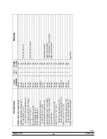
Page 43: ...NDLE A DRAW C602 X56421 1 3 103 O RING 1 4 OD X 070W 50 DURO 015872 3 000 SCREW ADJUSTMENT 5 16 24 602 056332 3 103 PIN HANDLE TWIN C712 C717 059894 1 103 PLUG PRIME TWIN C712 C713 059936 2 103 O RING 1 2OD X 070W 024278 4 000 VALVE A DRAW C712 C713 X59843 2 103 O RING 7 8 OD X 103W 014402 4 000 VALVE A DRAW CENTER X62218 1 103 O RING 7 8 OD X 103W 014402 1 000 SEAL DRAW VALVE 034698 1 000 DRYER C...

Page 44: ...ESS WIRE LW V CNTL CHNNL 062049 1 103 HARNESS WIRE LW V MIX HOPPER 062050 1 103 HARNESS WIRE POWER SWITCH 062051 1 103 HINGE A MOTOR 632 8756 ALT X25736 2 103 JACK A FLAVORBURST C706 X56353 2 103 KIT A TUNE UP 3 SPT C713 X49463 80 1 000 CAP DESIGN 1 010 ID 6 POINT 014218 3 000 O RING 7 8 OD X 103W 014402 6 000 O RING 643 OD X 077W 018572 8 000 O RING 1 2OD X 070W 024278 4 000 SEAL DRIVE SHAFT 0325...

Page 45: ...ANEL A FRONT C712 C717 X59836 1 103 UPPER FRONT W NOSE CONE PANEL A FRONT LOWER X59854 1 103 PANEL CORNER FRNT R C712 C717 063087 1 103 REPLACES 059882 PANEL CORNER FRNT L C712 C717 063088 1 103 REPLACES 059882 PANEL REAR C713 C717 059917 1 103 PANEL SIDE LEFT C712 C717 059906 1 103 PANEL SIDE RIGHT C712 C717 059907 1 103 PCB A CONTROL C713 UVC3 SM X62291 SER 1 212 CONTROL UVC3 SURFACE MOUNT 05918...

Page 46: ... 002201 2 000 DEC PLATE SCREW 5 16 18X2 1 2 HEX CAP 002498 8 000 B M MOUNT SCREW 10 32X3 8 RHM ZP 002742 8 000 LOUVERS SCREW 1 4 20X3 8 RHM STNLS 011694 14 000 PANELS SCREW 8X3 8 RD HD TYP B 013234 2 000 CORNER TRIM SCREW 5 16 18X1 3 4 HEX CAP 019691 10 NNN COMP L R SHAFT BEATER 032564 2 103 SEAL DRIVE SHAFT 032560 2 000 SHELL A INSULATED C713 X63337 SER 1 512 STUD NOSE CONE 055987 4 103 SHIELD SP...

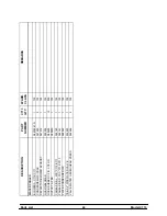
Page 47: ...7 1 103 TUBE A FEED SS 3 16 HOLE DIA X29429 3 2 103 O RING 643 OD X 077W 018572 8 000 VALVE ACCESS 1 4 MFLX1 4 S 90 047016 1 103 DANFOSS ACCESS VALVE ACCESS 1 4FL X 1 4SOLDER 044404 1 103 LINE SUCTION DNFS VALVE ACCESS 1 4MFL X 3 8ODSDR 053565 4 103 LINE DISCHARGE LINE ACCESS VALVE EPR 1 4S 022665 1 103 LINE SUCTION DNFS VALVE EXP AUTO 1 4S X1 4 FPT 046365 2 103 VALVE A AXV L C712 C713 X63349 1 10...

Page 48: ...AX 047540 2 103 DEFLECTOR BLOWER EXHAUST 047912 1 103 GUARD BLOWER 022505 1 103 HOSE RUBBER 1 2 ID X 7 8 OD R50200 15 000 OUTLET A TEE X25900 1 103 PANEL SIDE L W C C712 C717 062160 1 103 PANEL SIDE R W C C712 C717 062161 1 103 PLATE CONDENSER W C 062043 1 103 TEE 3 8 PIPE WATER VALVE 032953 1 103 VALVE WATER 3 8 REG HEAD PRESS 046686 2 103 ...

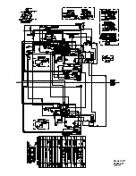
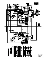
Page 49: ...Model C713 059899 27 7 25 11 ...

Page 50: ...Model C713 059899 33 7 25 11 ...

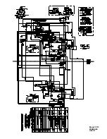
Page 51: ...Model C713 059899 40 7 25 11 ...

Page 52: ...Model C713 059899 58 7 25 11 ...

Reviews: