5-4
USER INTERFACE
087482-M
User Interface
5
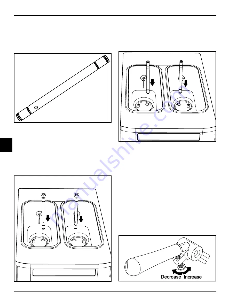
Feed Tube
The feed tube maintains over-run and allows enough mix
to enter the freezing cylinder after a draw. One end of the
tube has a mix delivery hole on the side, and the other
end does not.
Figure 5-4
The feed tube serves two purposes.
•
Normal Operation:
After priming the machine, the
end of the feed tube with the mix delivery hole is
placed in the mix inlet hole, and the air orifice is
installed. Every time the draw handle is raised, new
mix and air from the hopper will flow down into the
freezing cylinder. This will keep the freezing cylinder
properly loaded and will maintain overrun.
Figure 5-5
•
Standby Operation:
During long “no sale” periods,
the air orifice is removed and the feed tube is
inverted. The end of the feed tube without the mix
delivery hole is placed in the mix inlet hole to prevent
mix from entering the freezing cylinder.
Figure 5-6
Note:
Make sure the level of mix is below the mix
delivery hole in the side of the feed tube. Failure to follow
this instruction may result in lower product quality when
normal operation is resumed.
Adjustable Draw Handle
These units feature an adjustable draw handle to provide
the best portion control, giving a better, consistent quality
to your product and controlling costs. The draw handle
should be adjusted to provide a flow rate of 5 oz. to
7-1/2 oz. (142 g to 213 g) of product by weight per 10
seconds. To
increase
the flow rate, tighten the screw. To
decrease
the flow rate, loosen the screw.
Important!
When dispensing product, pull only one draw
handle at a time.
Figure 5-7
30124
30123
30121
Summary of Contents for C791
Page 8: ...1 4 TO THE INSTALLER 087482 M To the Installer 1 ...
Page 38: ...9 2 PARTS REPLACEMENT SCHEDULE 087482 M Parts Replacement Schedule 9 Notes ...
Page 42: ...10 4 LIMITED WARRANTY ON EQUIPMENT 087482 M Limited Warranty on 10 Notes ...
Page 46: ...11 4 LIMITED WARRANTY ON PARTS 087482 M Limited Warranty on Parts 11 Notes ...


