background image

V

-

21A


INTRODUCTION TO STUDWELDING


7


The Taylor Studwelding DA6 HI

-

LIFT studwelding pistol when matched with an appropriate 

controller and earth cables is intended for accurate stud welding up to 30 mm diameter 
studs. The pistol is lightweight, ergonomic and has been designed to operate with a 
minimum amount of maintenance. The DA6 HI

-

LIFT has been specifically designed to have 

an increased lift capacity especially when welding with increased protrusion e.g. When 
welding shear connectors (concrete anchors) thru

-

deck.


The energy required to carry out the welding operation is derived from an appropriate 
studwelding controller.


Taylor Studwelding Systems Ltd controllers are modern, robustly designed and offer 
maximum reliability combined with an easy to understand operator interface.


THE PROCESS


The process of drawn arc studwelding is long established and well proven. The basic steps 
are as follows :


• 

A measured amount of weld stud protrusion is set at the welding pistol.


• 

Once in position, the pistol lifts the stud away from the work

-

piece, simultaneously 

striking an arc between the two.


• 

Both the tip of the weld stud and the surface of the work

-

piece melt as the arc is 

sustained for a pre

-

determined interval.


• 

At the completion of the pre

-

determined interval, the pistol returns the weld stud to 

the molten pool on the work

-

piece, thus forming a weld.


The most common and traditional drawn arc welds have a weld duration greater than 
100ms and employ the use of a single use ceramic arc shield, commonly referred to as a 
ferrule. This ferrule helps to protect the arc during the weld and assists in formation of the 
final fillet. Post welding the ferrule is removed and disposed of.


Summary of Contents for DA4

Page 1: ...V 21A OPERATING GUIDE FOR TYPES DA4 DA5 DA6 HI LIFT DRAWN ARC PISTOL TAYLOR STUDWELDING SYSTEMS LIMITED A TAYLORMADE DRAWN ARC STUDWELDING PISTOL...

Page 2: ...2 PAGE No CONTENT 3 USEFUL INFORMATION 5 IMPORTANT SAFETY INFORMATION 7 INTRODUCTION TO STUDWELDING 8 SETTING UP AND WELDING 11 EXPLODED DIAGRAMS AND PARTS LISTINGS 18 ACCESSORIES 21 EC DECLARATION OF...

Page 3: ...44 0 1924 487701 You may wish to record the details of your controller below as this information will help with any technical assistance you may require PURPOSE AND CONTENT OF THIS GUIDE This guide h...

Page 4: ...t is sold passed on please hand over this manual to the new owner and if possible please inform us of the name and address of the new owner in case we need to contact him regarding the safety of the m...

Page 5: ...nnel working in close proximity must wear suitable eye ear and body protection Fumes and gases can seriously harm your health Use the equipment only in a suitably ventilated area If ventilation is ina...

Page 6: ...o not install connecting cables near heat sources or via traffic routes where people may trip over them or they may be damaged by the passage of vehicles forklifts etc 7 INTERFERENCE During welding op...

Page 7: ...ith an easy to understand operator interface THE PROCESS The process of drawn arc studwelding is long established and well proven The basic steps are as follows A measured amount of weld stud protrusi...

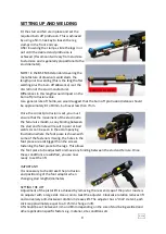
Page 8: ...hen ordering All three options shown perform the same task but are better suited to particular applications Fig 1 shows an extended foot arrangement which is favoured by many when performing thru deck...

Page 9: ...is smooth as any binding between the stud and ferrule will result in poor or bad welds As can be seen in the accompanying illustration where the foot piece is shown with some of the fasteners missing...

Page 10: ...seful information including stud welding techniques weld testing and inspection can also be found in the controller operating guide PLEASE NOTE Information contained in this operating guide is intende...

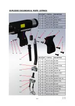
Page 11: ...WELDING CABLE m DA5 or 5 71 300 005 70mm WELDING CABLE m DA4 3 1 71 101 030 4 PIN CONTROL PLUG 4 1 81 101 163 WELDING PLUG DA6 or 1 81 101 149 WELDING PLUG DA4 DA5 5 5 71 101 032 CABLE CLIP NOT SHOWN...

Page 12: ...5 1 81 101 045 HANDLE COVER ITEM QTY PART No DESCRIPTION 6 1 Z120 05 025 SCREW 7 2 Z120 05 020 SCREW 8 1 81 101 125 PUSHBUTTON 9 1 81 101 030 SPRING 10 1 81 101 089 ACTUATOR 11 1 81 101 054 CABLE SLE...

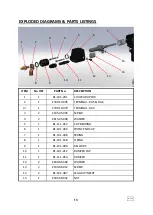
Page 13: ...L DA4 3 2 Z105 05 035 SCREW 4 2 Z615 05 000 WASHER 5 1 81 111 052 CLIP BEARING 6 1 81 101 399 FRONT END CAP 7 1 81 101 398 SPRING 8 1 81 101 168 O RING 9 1 81 101 006 BELLOWS 10 1 81 101 212 DAMPER CA...

Page 14: ...ESCRIPTION 1 1 81 101 208 SHAFT FRONT 2 1 81 101 065 INSULATOR 3 1 Z105 05 055 SCREW 4 1 81 101 391 INSULATOR 5 1 81 101 394 SHAFT BLOCK 6 1 81 101 071 INSULATOR 7 1 81 101 073 LIFTING SLEEVE 8 1 81 1...

Page 15: ...S PARTS LISTINGS 15 6 4 5 2 3 1 ITEM No OFF PART No DESCRIPTION 1 4 Z220 04 010 SCREW 2 1 81 101 014 RETAINING PLATE 3 1 81 101 015 LIFTING RING 4 1 81 101 018 SPRING 5 2 81 101 250 BEARING BUSH 6 1 8...

Page 16: ...TEM No OFF PART No DESCRIPTION 1 1 81 101 023 PISTOL HALF MOULDING 2 1 81 101 397 BODY CLAMPING RING 3 1 81 101 101 REAR END CAP 4 1 81 101 024 PISTOL HALF MOULDING 5 1 Z100 04 025 SCREW 6 2 Z800 03 0...

Page 17: ...IPTION 1 1 81 101 390 COIL HOUSING 2 1 81 101 389 LIFT COIL 3 1 81 101 039 WAVE SPRING 4 1 81 101 043 DETENT HOUSING 5 1 81 101 104 COIL LOCKING RING 6 4 Z410 05 020 SET SCREW 7 1 81 101 376 SPRING 8...

Page 18: ...022 22mm SHEAR CONNECTOR CHUCK 87 101 025 25mm SHEAR CONNECTOR CHUCK PART No DESCRIPTION 89 101 270 12mm FOOT PIECE 89 101 257 16mm FOOT PIECE 89 101 258 19mm FOOT PIECE 89 101 250 22mm FOOT PIECE 89...

Page 19: ...WASHER 3 1 SEE BELOW C PIECE 4 1 SEE BELOW STEM BUTTERFLY ASSEMBLY 5 2 81 111 029 LEG 6 2 Z105 05 016 SCREW 5 3 4 1 2 6 19 PART No DESCRIPTION 89 101 800 STEM BUTTERFLY ASSEMBLY PART No DESCRIPTION 8...

Page 20: ...DAPTOR 5 2 81 111 029 LEG 6 2 Z410 05 010 SET SCREW 5 3 4 1 2 6 ACCESSORIES TO BEAM FOOT ASSEMBLY 20 PART No DESCRIPTION 87 101 026 19mm TO BEAM FOOT ASSEMBLY 87 101 027 22mm TO BEAM FOOT ASSEMBLY 87...

Page 21: ...y Directive The above mentioned products conform to the following European standards EN 60974 1 2012 ARC WELDING EQUIPMENT PART 1 WELDING POWER SOURCES EN 60974 10 2014 ARC WELDING EQUIPMENT PART 10 E...

Reviews: