24
Models 8752, 8756, 8757
Operating Procedures
150422
Air/Mix Pump Assembly
The purpose of the air/mix pump is to meter a specific
amount of air and mix and transfer this combination to
the freezing cylinder.
Refer to the illustration on page 28 for identification of
parts during assembly.
Step 1
Inspect the rubber and plastic pump parts. The
o
−
rings, check ring, and gasket must be in 100% good
condition for the pump and entire machine to operate
properly. They cannot properly serve their intended
function if nicks, cuts, or holes in the material are
present.
Inspect the plastic pump parts for cracks, wear, and
de
−
lamination of plastic.
Replace any defective parts immediately and discard
the old.
Step 2
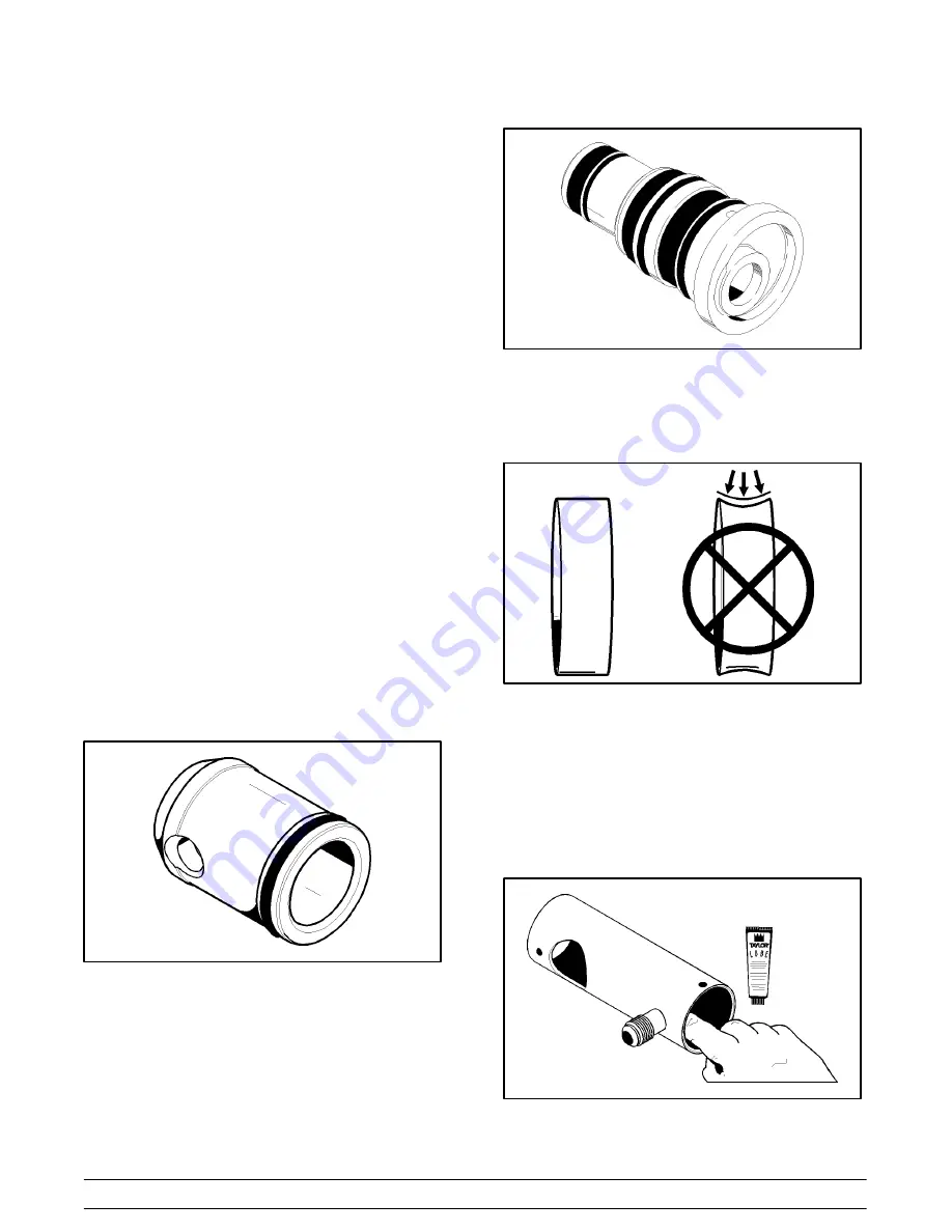
Assemble the piston. Slide the o
−
ring into the groove
on the piston.
DO NOT
lubricate this o
−
ring.
Figure 24
Step 3
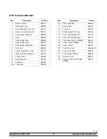
Assemble the liquid valve body. Slide the three check
bands and three o
−
rings into the grooves on the liquid
valve body.
DO NOT
lubricate the check bands or
o
−
rings.
Figure 25
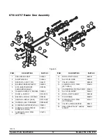
Note:
Check bands have two smooth surfaces. A
concave shape indicates an incorrect assembly. Turn
the check band inside out to correctly expose the flat
surface.
Figure 26
Step 4
Put a small amount of lubricant inside the piston and
insert the liquid valve body into the piston.
Apply a small amount of lubricant to the
lower
inside
diameter of the pump cylinder to a depth equivalent to
the length of your index finger. Once applied, the
amount of lubricant should be equal to a paper
−
thin
film.
Figure 27


