6-8
OPERATING PROCEDURES
Model 8756
Operating Procedures
6
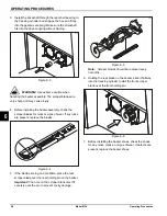
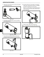
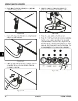
9. Slide the O-ring into the groove on the mix inlet fitting
and lubricate the O-ring.
Figure 6-30
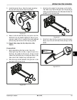
10. Insert the mix inlet fitting into the hole in the base of
the liquid valve body.
Figure 6-31
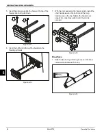
11. Secure the pump parts by sliding the keeper pin
through the holes at the bottom of the pump body.
Figure 6-32
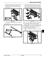
12. Assemble the flare line and suction line. Attach the
suction line to the barbed end of the mix inlet fitting
and allow the weighted end to hang freely.
Attach one end of the flare line to the threaded fitting
on the lower side of the pump body. Allow the other
end to hang freely.
Figure 6-33
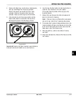
13. Place the pump collar over the pump body.
Note:
The crossholes of the pump collar will be on top.
Figure 6-34
15047
Apply the appropriate
Taylor approved food safe lubricant.
15048
15049
15097
15022
Summary of Contents for Horizon 8756
Page 18: ...4 6 OPERATOR PARTS IDENTIFICATION Model 8756 Operator Parts Identification 4 Notes ...
Page 22: ...5 4 USER INTERFACE Model 8756 User Interface 5 Notes ...
Page 40: ...6 18 OPERATING PROCEDURES Model 8756 Operating Procedures 6 Notes ...
Page 46: ...8 4 TROUBLESHOOTING GUIDE Model 8756 Troubleshooting Guide 8 Notes ...
Page 48: ...9 2 PARTS REPLACEMENT SCHEDULE Model 8756 Parts Replacement Schedule 9 Notes ...
Page 52: ...10 4 LIMITED WARRANTY ON EQUIPMENT Model 8756 Limited Warranty on Equipment 10 Notes ...
Page 56: ...11 4 LIMITED WARRANTY ON PARTS Model 8756 Limited Warranty on Parts 11 Notes ...
Page 58: ...12 2 WIRING DIAGRAMS Model 8756 Wiring Diagrams 12 Notes ...

