6-16
OPERATING PROCEDURES
Model 8756
Operating Procedures
6
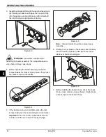
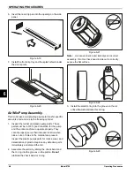
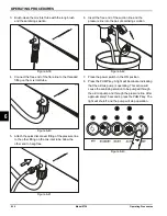
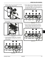
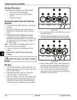
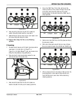
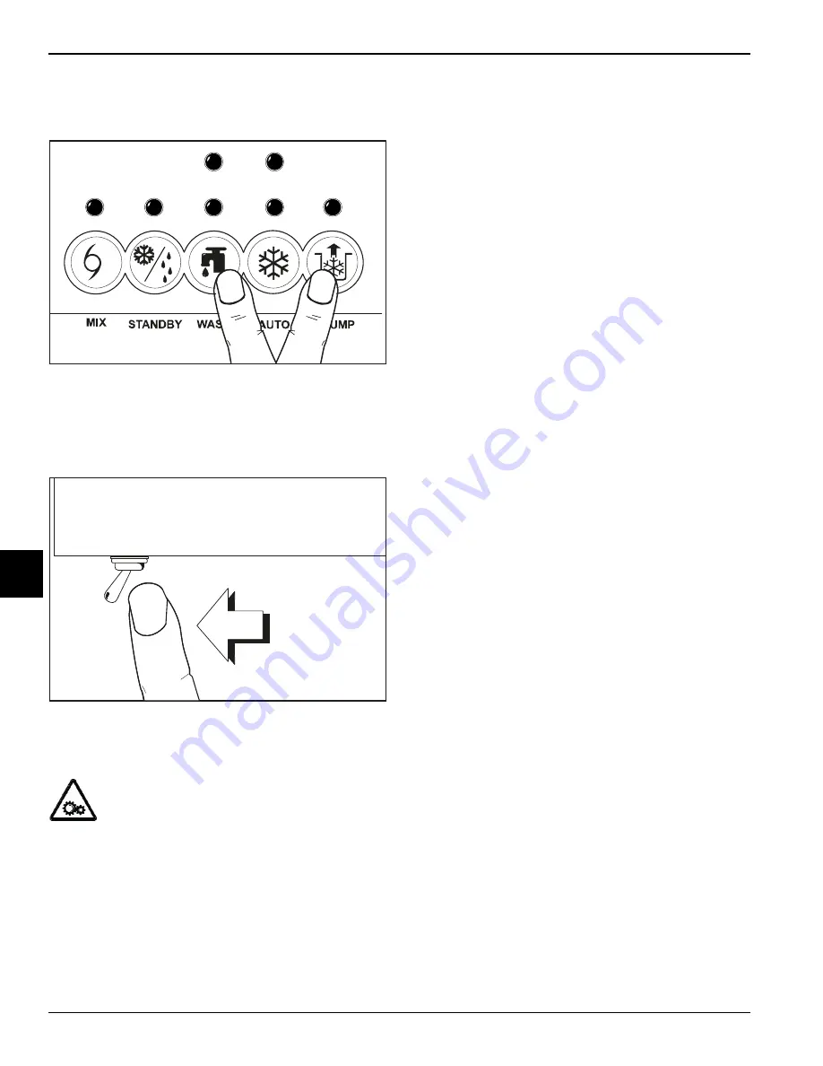
8. Once the solution stops flowing from the door spout,
close the draw valve and press the WASH and
PUMP keys to stop operation.
Figure 6-63
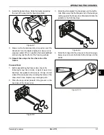
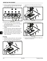
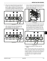
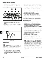
9. Repeat these steps for the other side of the
freezer.
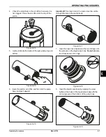
10. Place the power switch in the OFF position before
disassembling the machine.
Figure 6-64
Disassembly
WARNING!
Make sure the power switch is in
the OFF position. Failure to follow this instruction may
result in severe personal injury from hazardous moving
parts.
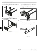
1. Remove the handscrews, freezer door, beaters,
shoes, scraper blades, and driveshafts from the
freezing cylinders. Take these parts to the sink for
cleaning.
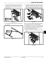
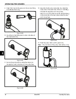
2. Remove the air/mix pump. Unscrew the flare line
from the mix inlet tube. Disengage the pressure line
from the pressure switch and the mix inlet tube. Pull
the retaining pin out of the pump collar and slide the
collar down. Tilt the air/mix pump away from the
machine and take the entire assembly to the sink for
further disassembly and brush-cleaning.Take these
parts to the sink for cleaning.
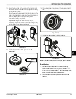
3. Remove the pressure switch cap from the mix
cabinet. Remove the diaphragm from the cap.
4.
Repeat steps 3 and 4 for the other side of the
freezer.
5. Remove the front drip tray and the splash shield.
Brush-Cleaning
1. Prepare a sink with an approved cleaning solution
(examples: Kay-5
®
or Stera-Sheen
®
). Use warm
water and follow the manufacturer's specifications.
If an approved cleaner other than Kay-5® or
Stera-Sheen
®
is used, dilute it according to the label
instructions.
Important!
Follow the label directions. Too
strong
of
a solution can cause parts damage, and too
mild
of a
solution will not provide adequate cleaning. Make
sure all brushes provided with the freezer are
available for brush-cleaning.
2. Remove the seals from the driveshafts.
3. Remove the following from the freezer doors:
gaskets, front bearings, pivot pins, draw handles,
draw valves, prime plugs, and design caps. Remove
all O-rings.
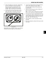
Note:
To remove the O-rings, use a single-service
towel to grasp the O-ring. Apply pressure upward
until the O-ring pops out of its groove. With the other
hand, push the top of the O-ring forward. It will roll
out of the groove and can be easily removed. If there
is more than one O-ring to be removed, always
remove the rear O-ring first. This will allow the O-ring
to slide over the forward rings without falling into the
open grooves.
13038wp
13003
Summary of Contents for Horizon 8756
Page 18: ...4 6 OPERATOR PARTS IDENTIFICATION Model 8756 Operator Parts Identification 4 Notes ...
Page 22: ...5 4 USER INTERFACE Model 8756 User Interface 5 Notes ...
Page 40: ...6 18 OPERATING PROCEDURES Model 8756 Operating Procedures 6 Notes ...
Page 46: ...8 4 TROUBLESHOOTING GUIDE Model 8756 Troubleshooting Guide 8 Notes ...
Page 48: ...9 2 PARTS REPLACEMENT SCHEDULE Model 8756 Parts Replacement Schedule 9 Notes ...
Page 52: ...10 4 LIMITED WARRANTY ON EQUIPMENT Model 8756 Limited Warranty on Equipment 10 Notes ...
Page 56: ...11 4 LIMITED WARRANTY ON PARTS Model 8756 Limited Warranty on Parts 11 Notes ...
Page 58: ...12 2 WIRING DIAGRAMS Model 8756 Wiring Diagrams 12 Notes ...

