6-6
OPERATING PROCEDURES
Model 8756
Operating Procedures
6
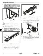
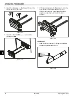
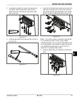
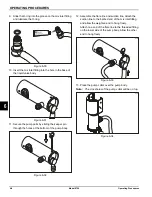
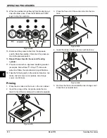
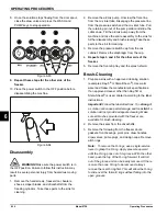
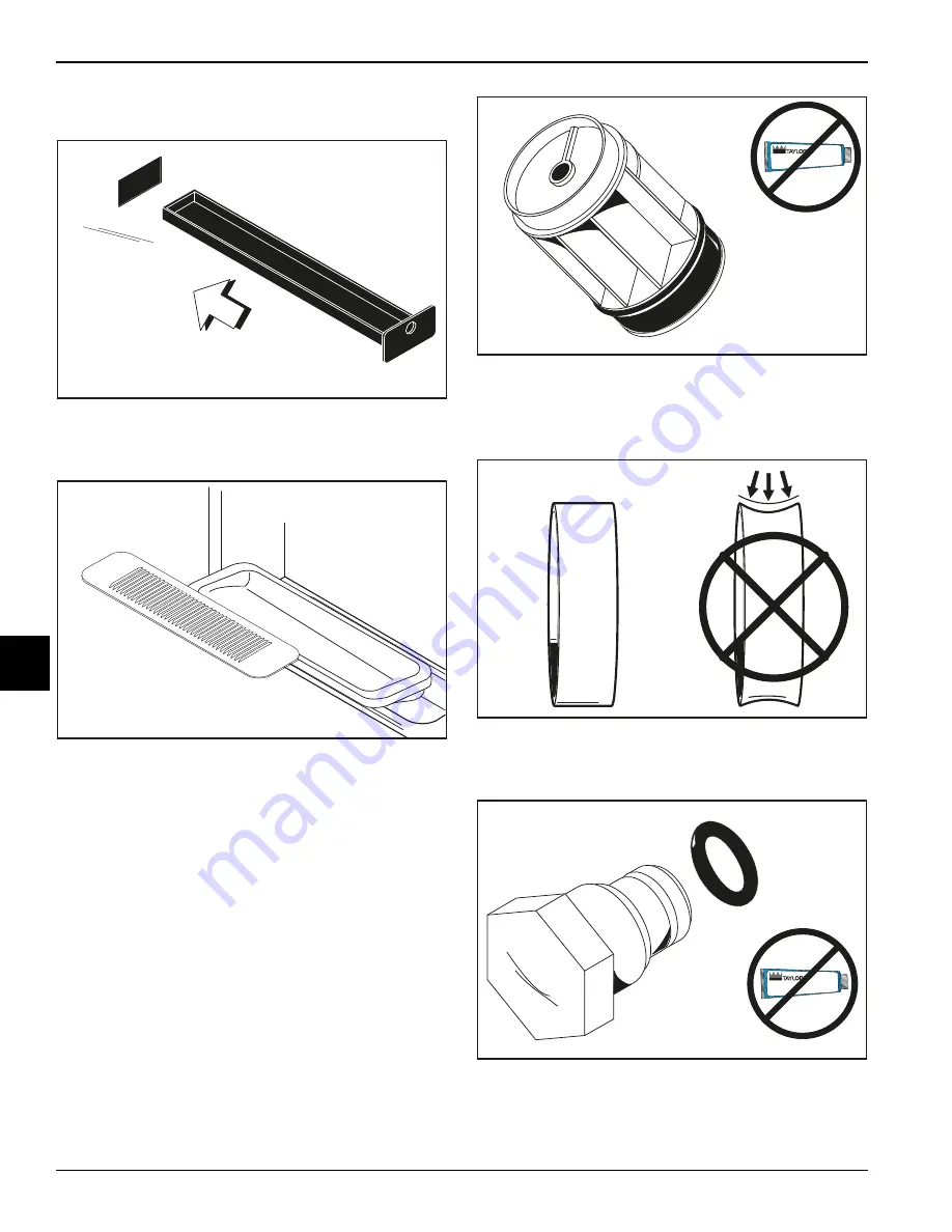
6. Insert the rear drip pan into the opening on the side
panel.
Figure 6-19
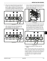
7. Install the front drip tray and the splash shield under
the door spouts.
Figure 6-20
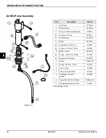
Air/Mix Pump Assembly
This model uses a single-stage pump to transfer specific
amounts of air and mix to the freezing cylinder.
1. Inspect the rubber and plastic pump parts. These
parts must be in 100% good condition for the pump
and the entire machine to operate properly. They
cannot properly serve their intended function when
nicks, cuts, or holes in the material are present.
Inspect the plastic pumps parts for cracks, wear, and
delamination of plastic. Replace any defective parts
immediately and discard the old.
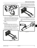
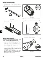
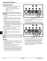
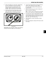
2. Assemble the piston by sliding the check band and
the O-ring into the grooves on the piston.
Do not
lubricate the check band or O-ring.
Figure 6-21
Note:
A concave check band indicates an incorrect
assembly. Turn the check band inside out to correctly
expose the flat surface.
.
Figure 6-22
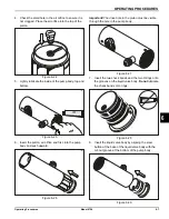
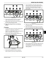
3. Install the small O-ring into the groove on the air
orifice.
Do not
lubricate this O-ring.
Figure 6-23
10176i
10338
Apply the appropriate
Taylor approved food safe lubricant.
15045
15041
Apply the appropriate
Taylor approved food safe lubricant.
15050
Summary of Contents for Horizon 8756
Page 18: ...4 6 OPERATOR PARTS IDENTIFICATION Model 8756 Operator Parts Identification 4 Notes ...
Page 22: ...5 4 USER INTERFACE Model 8756 User Interface 5 Notes ...
Page 40: ...6 18 OPERATING PROCEDURES Model 8756 Operating Procedures 6 Notes ...
Page 46: ...8 4 TROUBLESHOOTING GUIDE Model 8756 Troubleshooting Guide 8 Notes ...
Page 48: ...9 2 PARTS REPLACEMENT SCHEDULE Model 8756 Parts Replacement Schedule 9 Notes ...
Page 52: ...10 4 LIMITED WARRANTY ON EQUIPMENT Model 8756 Limited Warranty on Equipment 10 Notes ...
Page 56: ...11 4 LIMITED WARRANTY ON PARTS Model 8756 Limited Warranty on Parts 11 Notes ...
Page 58: ...12 2 WIRING DIAGRAMS Model 8756 Wiring Diagrams 12 Notes ...

