background image

2-2  

TO THE OPERATOR

Model SB25

To the Operator 

Notes:

Summary of Contents for SB25

Page 1: ...OPERATOR S MANUAL Model SB25 Blended Ice Machine 4 21 14 Original Publication Updated 9 20 2019 Original Operating Instructions 081218 M...

Page 2: ..._______________ Serial Number ____________________________________________________________ Electrical Specs Voltage__________________ Cycle__________ Phase__________________________________ Maximum Fu...

Page 3: ...essories 4 3 Section 5 User Interface Recipe Upload Procedure 5 3 Calibration Procedures 5 4 Section 6 Operating Procedures Assembly and Setup 6 1 Basic Operation 6 1 4 Hour Cleaning Procedure 6 2 Dai...

Page 4: ...ii 081218 M Table of Contents Section 8 Troubleshooting Guide Section 9 Parts Replacement Schedule Section 10 Limited Warranty on Equipment Section 11 Limited Warranty on Parts...

Page 5: ...ock or hazardous moving parts as well as poor performance or damage to the machine WARNING This machine has many sharp edges that can cause severe injuries Site Preparation Review the area where the m...

Page 6: ...he nearest drain that can accommodate a 1 1 8 in 28 575 mm diameter drain tube A minimum of 1 in 25 mm air gap is required between the end of the drain tube and the drain to ensure proper flow The dra...

Page 7: ...for long periods or during initial installation shall have protective devices to protect against the leakage of current such as a GFI installed by authorized personnel to local codes Supply cords use...

Page 8: ...1 4 TO THE INSTALLER Model SB25 To the Installer 1 Notes...

Page 9: ...t all personnel understand their role in using and maintaining the machine If you require technical assistance please contact your local authorized Taylor distributor Note Your Taylor warranty is vali...

Page 10: ...2 2 TO THE OPERATOR Model SB25 To the Operator 2 Notes...

Page 11: ...he machine Failure to follow this instruction may result in electrocution WARNING Avoid injury DO NOT operate the machine unless it is properly grounded DO NOT operate the machine with fuses larger th...

Page 12: ...he 2 water lines from the back of the machine Disconnect the cane pump line from the back of the machine 115V 60 Hz machines only IMPORTANT Access to the service area of the machine must be restricted...

Page 13: ...Section 4 4 1 Model SB25 Operator Parts Identification 4 Operator Parts Identification SB25 Exploded View Figure 4 1 1 2 14 3 4 5 7 8 9 11 10 12 6 16 17 13 15...

Page 14: ...5 Rod Pivot Actuator 081220 6 Actuator Rinse 081221 7 Grate Left 081228 8 Guard Splash 081122 9 Chute Shaver 081121 Item Description Part No 10 Lid Pour Pitcher 115V 081248 11 Pitcher Blender Unguarde...

Page 15: ...Figure 4 2 Not Shown 1a 1b 2 3 1 Item Description Part No 1 Kit A Brush X68468 1a Brush End Door Spout SS 039719 1b Brush Mix Pump Body 3 X 7 White 023316 1c Brush Mix Tube 068460 Item Description Pa...

Page 16: ...4 4 OPERATOR PARTS IDENTIFICATION Model SB25 Operator Parts Identification 4 Notes...

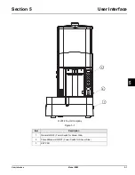
Page 17: ...5 1 Model SB25 User Interface 5 User Interface 2014 Taylor Company Figure 5 1 Item Description 1 Rinser ON OFF Power Switch for Rinser Side 2 Shaver Blender ON OFF Power Switch for Shaver Side 3 KEY...

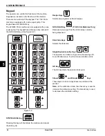
Page 18: ...ey will shut down the machine and cancel the drink cycle Recipe Keys Selects pre programmed flavor recipes NO SUGAR Key 115V 60 Hz Machines Only Removes cane sugar from the drink recipe currently bein...

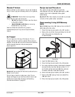
Page 19: ...sed and sanitized during the Daily Cleaning and Sanitizing Procedures described on page 6 3 Recipe Upload Procedure The customer recipe information is held in the microprocessor memory Recipes distrib...

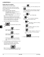
Page 20: ...blink Press the recipe key to change the Shave calibration value Press the recipe key to change the Water calibration value Press the recipe key to change the Cane calibration value 115V 60 Hz machin...

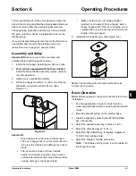
Page 21: ...he use of bagged ice is not recommended as it can jam the machine and damage the shaver blade The ice must be clean and free of debris Failure to follow this instruction may result in contaminated pro...

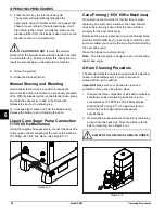
Page 22: ...e quick connect coupling at the rear of the machine The fitting will click into place See Figure 6 3 Figure 6 3 Cane Priming 115V 60 Hz Machines When starting the machine for the first time or when re...

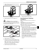
Page 23: ...7 8 Return the pitchers to the machine Daily Cleaning and Sanitizing Procedures Note This procedure must be done at the close of business Important Make sure your hands are clean and sanitized before...

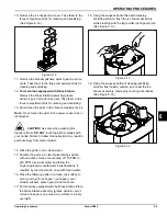
Page 24: ...des that are very sharp Failure to follow this instruction may result in contaminated product or personal injury from blade contact Figure 6 9 6 Reinstall the ice hopper cover See Figure 6 10 Figure 6...

Page 25: ...rom blade contact 14 Rinse the parts in cool clean water 15 Sanitize the parts in a cleaning sanitizing solution with an active chlorine concentrate of 100 PPM to 200 PPM Use warm water and follow the...

Page 26: ...n the dispensing tubes 25 If required by your local code repeat the previous step using clean water 26 Repeatedly dip the spout brush into the pail of cleaning sanitizing solution and very carefully b...

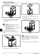
Page 27: ...5 Remove the dip tube from the cane sugar container or disconnect it from the BIB Place the dip tube in the pail filled with warm water 6 Place the blender pitcher on the blender base Note Remove and...

Page 28: ...6 8 OPERATING PROCEDURES Model SB25 Operating Procedures 6 Notes...

Page 29: ...d be stressed during the cleaning and sanitizing operations Troubleshooting Bacterial Count Thoroughly clean and sanitize the machine regularly including complete disassembly and brush cleaning Use al...

Page 30: ...7 2 OPERATOR S CHECKLIST Model SB25 Operator s Checklist 7 Notes...

Page 31: ...e technician d Broken fitting d Contact a Taylor service technician e Pump is not working e Contact a Taylor service technician 6 Recipe key 1 fast blink hopper lid sensor fault a Hopper cover is not...

Page 32: ...r pitcher is damaged a Abuse or excessive wear a Replace the blender pitcher PROBLEM PROBABLE CAUSE REMEDY 19 Machine will not rinse a The power switch is in the OFF position a Place the power switch...

Page 33: ...e 9 Parts Replacement Schedule Table 9 1 Must be replaced by an authorized service technician Description Every 3 Months Every 6 Months Annually Brushes Inspect and Replace if Necessary Minimum Shaver...

Page 34: ...9 2 PARTS REPLACEMENT SCHEDULE Model SB25 Parts Replacement Schedule 9 Notes...

Page 35: ...cated by the Product serial number Proof of purchase may be required at time of service 2 This limited warranty is valid only if the Product is installed and all required service work on the Product i...

Page 36: ...roduct s data label will void this limited warranty 13 Any cost to replace refill or dispose of refrigerant including the cost of refrigerant 14 ANY SPECIAL INDIRECT OR CONSEQUENTIAL PROPERTY OR COMME...

Page 37: ...ed proof of purchase may be required at time of service 2 This limited warranty is valid only if the Part is installed and all required service work in connection with the Part is performed by an auth...

Page 38: ...arranty service work promptly upon arrival 9 Failure damage or repairs due to faulty installation misapplication abuse no or improper servicing unauthorized alteration or improper operation or use as...

Page 39: ...NCIDENTAL DAMAGES INCLUDING CLAIMS FOR LOST SALES LOST PROFITS PRODUCT LOSS PROPERTY DAMAGES OR SERVICE EXPENSES ARE EXPRESSLY EXCLUDED THE EXPRESS WARRANTIES MADE IN THIS LIMITED WARRANTY MAY NOT BE...

Page 40: ...11 4 LIMITED WARRANTY ON PARTS Model SB25 Limited Warranty on Parts 11 Notes...

Reviews: