6-7
6-7
THDC / THDCP - 954 / 955 / 974 (Rev. 06/03)
THDC / THDCP - 954 / 955 / 974 (Rev. 06/03)
4) completing the circuit of both sets of pins.
4) completing the circuit of both sets of pins.
When the relay is energized, the coil shifts the
When the relay is energized, the coil shifts the
switch, connecting pins (9 and 5) and pins (12 and
switch, connecting pins (9 and 5) and pins (12 and
8) completing the circuit of both sets of pins.
8) completing the circuit of both sets of pins.
The most effective way to troubleshoot this type
The most effective way to troubleshoot this type
relay is wi
relay is with an ohmmeter
th an ohmmeter.
. This can be accom-
This can be accom-
plished by removing the wires at relay socket ter-
plished by removing the wires at relay socket ter-
minals (12, 8, and 4) and terminals (9, 5, and 1).
minals (12, 8, and 4) and terminals (9, 5, and 1).
In a de-energized state, ensure that terminals (9
In a de-energized state, ensure that terminals (9
and 1) and terminals (12 and 4) have continuity
and 1) and terminals (12 and 4) have continuity
between them.
between them. With an ohmm
With an ohmmeter
eter, check the
, check the
resistance between terminals (9 and 1) and termi-
resistance between terminals (9 and 1) and termi-
nals (1
nals (12 and
2 and 4).
4). The ohmm
The ohmmeter shou
eter should indic
ld indicate a
ate a
read
reading of 0 - 40
ing of 0 - 40 ohms
ohms.
. Ener
Energize the re
gize the relay and
lay and
check the resistance between terminals (9 and 5)
check the resistance between terminals (9 and 5)
and termi
and terminals (12 and 8)
nals (12 and 8).
. The ohmmet
The ohmmeter should
er should
indi
indicate a readi
cate a reading of 0
ng of 0 - 40 ohms.
- 40 ohms. If thes
If these two
e two
chec
checks are good, th
ks are good, the relay is goo
e relay is good.
d. If one of
If one of
these checks fails and 12 VDC required at ter-
these checks fails and 12 VDC required at ter-
8
8
5
5
4
4
1
1
9
9
12
12
14
14
13
13
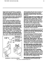
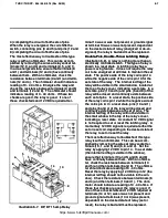
Illust
Illustration 6-7.
ration 6-7. DP
DP, DT 15 amp Relay
, DT 15 amp Relay
minal 14 was or was not present, or ground signal
minal 14 was or was not present, or ground signal
at terminal 13 was or was not present, dependant
at terminal 13 was or was not present, dependant
on the desired state of relay (energized or de-en-
on the desired state of relay (energized or de-en-
ergized), the relay is bad and must be replaced.
ergized), the relay is bad and must be replaced.
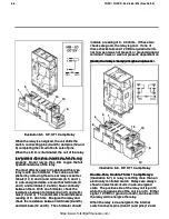
Double-Pole, Double-Throw Latching Relays
Double-Pole, Double-Throw Latching Relays
(Illustration 6-8)
(Illustration 6-8)
..
A relay is nothing more than an
A relay is nothing more than an
electri
electrically contr
cally controlled switc
olled switch.
h. This type of relay is
This type of relay is
show
shown in a
n in a res
reset stat
et state.
e. A latchi
A latching relay has a
ng relay has a
power savi
power saving feature.
ng feature. It does not requir
It does not require the relay
e the relay
coil to be energized at all times to maintain the set
coil to be energized at all times to maintain the set
state.
state. The positi
The positive side of the relay c
ve side of the relay coil is pin 14
oil is pin 14
while the negative side of the coil is pin 13 for the
while the negative side of the coil is pin 13 for the
set state of the rel
set state of the relay
ay.
. The internal r
The internal red flag of the
ed flag of the
relay will be visible in the small window, located at
relay will be visible in the small window, located at
the top of relay’s cov
the top of relay’s cover
er, indicating a set state.
, indicating a set state. In a
In a
set state, pins (10 and 5) and pins (6 and 8) of the
set state, pins (10 and 5) and pins (6 and 8) of the
relay will be closed and continuity exists between
relay will be closed and continuity exists between
each set of pins.
each set of pins. In a reset state, t
In a reset state, the positive s
he positive side
ide
of the relay coil is pin 12 while the negative side of
of the relay coil is pin 12 while the negative side of
the coi
the coil is pin 9.
l is pin 9. In a reset sta
In a reset state, pin
te, pins (10 and 1)
s (10 and 1)
and pins (6 and 4) of the relay will be closed and
and pins (6 and 4) of the relay will be closed and
continuit
continuity exists b
y exists between each set of pins
etween each set of pins.
. The
The
internal red flag of the relay will not be visible in
internal red flag of the relay will not be visible in
the small window in the top of the relay’s cover,
the small window in the top of the relay’s cover,
indicati
indicating a reset state.
ng a reset state. A constant 12 VDC si
A constant 12 VDC signal
gnal
is not required to set or reset the latc
is not required to set or reset the latching relay
hing relay.
. A
A
momentary 12 VDC signal is required at either the
momentary 12 VDC signal is required at either the
set or reset coil, depending on the desired state of
set or reset coil, depending on the desired state of
the relay, to set or reset the relay.
the relay, to set or reset the relay.
The most effective way to troubleshoot this type
The most effective way to troubleshoot this type
relay is wi
relay is with an ohmmeter
th an ohmmeter.
. This can be accom-
This can be accom-
plished by removing the wires at relay socket ter-
plished by removing the wires at relay socket ter-
min
minals (
als (10, 1, and 5) and (6, 8, an
10, 1, and 5) and (6, 8, and 4).
d 4). Set the
Set the
rel
relay by apply
ay by applying 12 VDC to pin 14.
ing 12 VDC to pin 14. In a set state
In a set state
(the internal red flag is visible in the window),
(the internal red flag is visible in the window),
ensure that terminals (10 and 5) and (6 and 8)
ensure that terminals (10 and 5) and (6 and 8)
have continui
have continuity between them.
ty between them. With an ohmm
With an ohmme-
e-
ter, check the resistance between terminals (10
ter, check the resistance between terminals (10
and 5) and then term
and 5) and then terminal
inals (6 and 8).
s (6 and 8). The ohm
The ohmme-
me-
ter should indicate a reading of 0 - 40 ohms.
ter should indicate a reading of 0 - 40 ohms.
Reset the relay by applying 12 VDC to pin 12 (the
Reset the relay by applying 12 VDC to pin 12 (the
internal red flag should not be visible in the win-
internal red flag should not be visible in the win-
dow).
dow). Check the resi
Check the resistance between term
stance between terminals (6
inals (6
and 4) and then term
and 4) and then terminal
inals (10 and 1).
s (10 and 1). The ohm
The ohm--
met
meter shoul
er should indic
d indicate a readin
ate a reading of 0
g of 0 - 40 ohms.
- 40 ohms. If
If
these four c
these four checks ar
hecks are good, the relay
e good, the relay is good.
is good. If
If
one of these checks fails and 12 VDC required at
one of these checks fails and 12 VDC required at
terminals (14 or 12) was or was not present and
terminals (14 or 12) was or was not present and
ground signal at terminals (13 or 9) was present,
ground signal at terminals (13 or 9) was present,
dependant on the desired state of relay (set or
dependant on the desired state of relay (set or
reset), the relay is bad and must be replaced.
reset), the relay is bad and must be replaced.
https://www.forkliftpdfmanuals.com/


