6-9
6-9
THDC / THDCP - 954 / 955 / 974 (Rev. 06/03)
THDC / THDCP - 954 / 955 / 974 (Rev. 06/03)
Single-Pole, Single-Throw, Maintain Contact
Single-Pole, Single-Throw, Maintain Contact
Switches.
Switches.
A switch is designed with the purpose
A switch is designed with the purpose
of controlling an electrical circuit by completing or
of controlling an electrical circuit by completing or
opening the circuit
opening the circuit.
. With an ohmmeter
With an ohmmeter, check the
, check the
resistance between the contact points of the
resistance between the contact points of the
swit
switch.
ch. With the swi
With the switch closed (com
tch closed (completing the
pleting the
circuit), the ohmmeter reading should indicate 0 -
circuit), the ohmmeter reading should indicate 0 -
40 ohms.
40 ohms. With the swi
With the switch open (opening the cir
tch open (opening the cir--
cuit), the ohmm
cuit), the ohmmeter reading should be infini
eter reading should be infinity
ty.
. If
If
the above chec
the above checks are good, the swi
ks are good, the switch is good.
tch is good. If
If
any of the above checks fail, the switch is bad and
any of the above checks fail, the switch is bad and
must be replaced.
must be replaced.
Single-Pole, Double-Throw, Momentary Rocker
Single-Pole, Double-Throw, Momentary Rocker
Switches.
Switches.
This type of switch operates on the
This type of switch operates on the
principle that the circuit is closed only when the
principle that the circuit is closed only when the
swit
switch is held in the clos
ch is held in the closed state.
ed state. Once the swit
Once the switch
ch
is released, the ci
is released, the circuit wi
rcuit will open.
ll open. This swi
This switch is
tch is
checked like an On-Off switch with the exception
checked like an On-Off switch with the exception
that the switch must be held closed to complete
that the switch must be held closed to complete
resistance checks.
resistance checks.
Solenoids.
Solenoids.
A solenoid is an electrical compo-
A solenoid is an electrical compo-
nent.
nent. When electr
When electricity
icity is applied to the coi
is applied to the coil, the
l, the
solenoid wi
solenoid will form an el
ll form an electromagnet
ectromagnet.
. The magnet-
The magnet-
ic field will pull or push an armature into the coil
ic field will pull or push an armature into the coil
(based on appli
(based on application).
cation). The armat
The armature can be con-
ure can be con-
nected to a switch in electrical circuits to turn the
nected to a switch in electrical circuits to turn the
swi
switch on or off.
tch on or off. An armat
An armature can also be used to
ure can also be used to
open or close valves.
open or close valves.
Solenoids employed as electrical switches can be
Solenoids employed as electrical switches can be
troublesh
troubleshot with an ohmmeter
ot with an ohmmeter.
. Remove the two
Remove the two
wires from the two larger posts of the solenoid.
wires from the two larger posts of the solenoid.
Energize the solenoi
Energize the solenoid.
d. With an ohmmeter
With an ohmmeter, check
, check
the resis
the resistance between the two l
tance between the two larger posts.
arger posts. The
The
ohmmeter should indicate between 0 - 40 ohms
ohmmeter should indicate between 0 - 40 ohms
nominally.
nominally.
Solenoids employed as hydraulic switches are
Solenoids employed as hydraulic switches are
used to open and clos
used to open and close spools of val
e spools of valves.
ves. The
The
simplest way to prove the solenoid coil good is to
simplest way to prove the solenoid coil good is to
energize the solenoid and then, with a metal
energize the solenoid and then, with a metal
object, touch the nut that secures the coil to the
object, touch the nut that secures the coil to the
cartri
cartridge.
dge. The magnetic f
The magnetic field generated when the
ield generated when the
coil becomes an electromagnet will be significant
coil becomes an electromagnet will be significant
enough to pull the metal object to the nut (some
enough to pull the metal object to the nut (some
solenoids employ a metal nut encased in plastic
solenoids employ a metal nut encased in plastic
and will require removal in order to detect the
and will require removal in order to detect the
magnetic fi
magnetic field).
eld). This wil
This will prove the coil good; how-
l prove the coil good; how-
ever
ever, the armature may be stuck
, the armature may be stuck.
. If the hydraulic
If the hydraulic
circuit is still defective at this point, remove the coil
circuit is still defective at this point, remove the coil
and cartri
and cartridge.
dge. Now energi
Now energize the coil, the arm
ze the coil, the arma-
a-
ture insi
ture inside the cartrid
de the cartridge should shift.
ge should shift. If the arma-
If the arma-
ture inside the cartridge did not shift and the coil is
ture inside the cartridge did not shift and the coil is
magnetize
magnetized,
d, replace the
replace the cartri
cartridge.
dge.
Exercise care not to reverse polarity because
Exercise care not to reverse polarity because
some solenoids employ internal diodes which can
some solenoids employ internal diodes which can
be destroyed when the pol
be destroyed when the polarity is r
arity is reversed.
eversed. The
The
solenoids employed on the transmission control
solenoids employed on the transmission control
valve contai
valve contain diodes.
n diodes. The black wi
The black wire of the coil
re of the coil
connects to the ground side of the circuit while the
connects to the ground side of the circuit while the
red wire goes to the positive side of the circuit.
red wire goes to the positive side of the circuit.
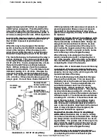
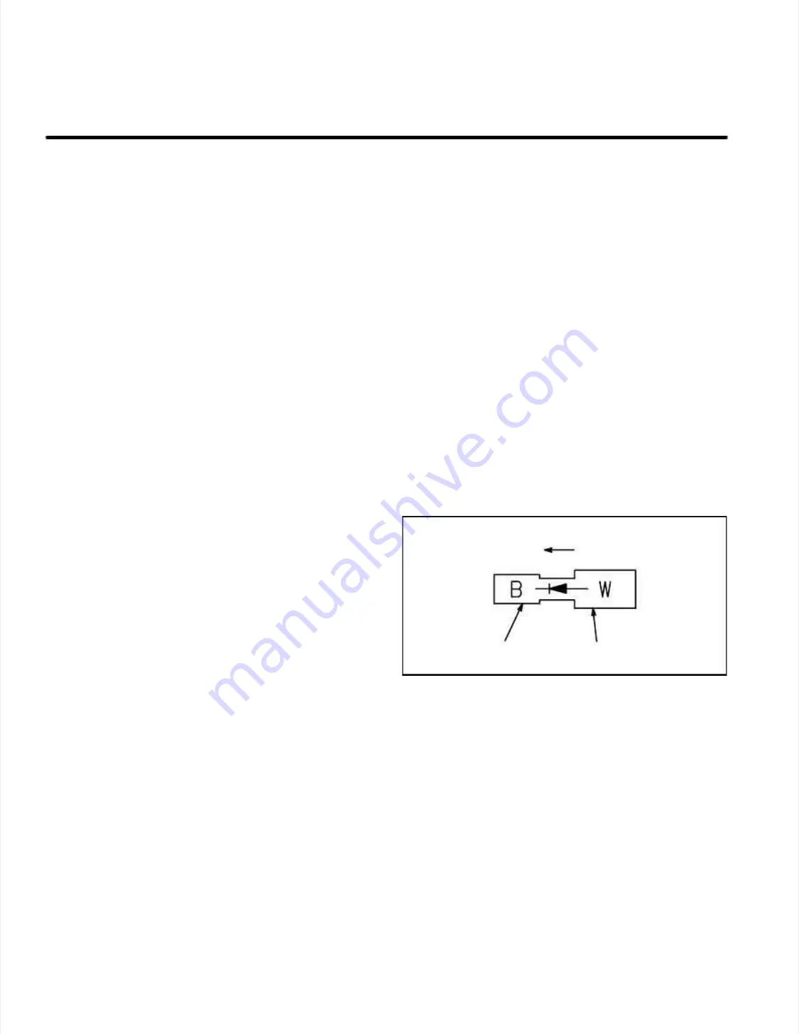
Diodes
Diodes
(Illustration 6-10)
(Illustration 6-10)
..
Diodes are one-way
Diodes are one-way
conductor
conductors that provide isolat
s that provide isolation.
ion. Current flo
Current flow
w
thr
through a diode is fro
ough a diode is from anode to catho
m anode to cathode.
de. They
They
are easily proven good by using an ohmmeter.
are easily proven good by using an ohmmeter.
When using the ohmmeter, place the leads of the
When using the ohmmeter, place the leads of the
ohmmeter on the opposite ends of the diode.
ohmmeter on the opposite ends of the diode.
Observe the ohmm
Observe the ohmmeter reading.
eter reading. Then revers
Then reverse the
e the
ohmmeter leads on the ends of the diode.
ohmmeter leads on the ends of the diode.
Observe t
Observe the ohmmeter
he ohmmeter reading.
reading. The ohmmet
The ohmmeter
er
readings should indicate a higher ohm resistance
readings should indicate a higher ohm resistance
in one direction opposed to the other direction
in one direction opposed to the other direction
because the current generated by the ohmmeter
because the current generated by the ohmmeter
is sufficient enough to forward-bias the diode.
is sufficient enough to forward-bias the diode.
C
Ca
atth
ho
od
de
e
A
An
no
od
de
e
Curren
Current t Flow
Flow
Illust
Illustration
ration 6-10.
6-10. Diode
Diode
https://www.forkliftpdfmanuals.com/

