12/ 42
Cylinder head
Assembly
1. Use a t-shaped sleeve -8# to remove the thermostat bolts, remove the thermostat, and remove the radiator
and
fan
case
cover (refer to the ZT1P52MI engine maintenance manual for disassembly and assembly - thermostat, radiator, fan case
cover).
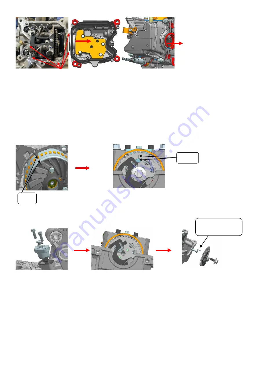
2. Put the 17#-t-shaped sleeve on the lock bolt of the magneto rotor, and then turn the crankshaft clockwise so that the marking
line at point t on the flywheel aligns with the arrow position in the figure. At the same time, the top dead center marking line on
the timing driven sprocket should also be aligned with the marking line on the camshaft bearing pressure plate.
Note: when turning the flywheel, once the marking line at point t turns over the marking line, it cannot be rotated in the
opposite direction. It is necessary to turn the crankshaft clockwise two times again to re-align the point! ! !
3. As shown in the picture, remove the tensioner with t bar-8#, remove the camshaft bolt with the jack sleeve head
14#, remove the timing driven sprocket, and the decompression lever
(tensioner refer to ZT1P52MI engine maintenance
manual for disassembly and assembly--cylinder head cover, cylinder head-tensioner).
4. As shown in the picture, first use t-bar-8# to remove 2 pieces of m6×105 hexagonal flange bolts on the side of the cylinder
head, and then use t-bar-12# to remove 4 pieces of m8×1.25 lock nuts on the opposite corners of the cylinder head, take off the
cylinder head, cylinder head gasket and positioning pin
(note: the removed cylinder head gasket cannot be used again)
.
align
align
Decompression
lever
apply sealant


