16
Owner’s Manual
COMPACT TILLER AND CULTIVATOR
Get parts online at
www.tazzoutdoorproducts.com
or Call
800-345-6007
M-F 8-5 CST
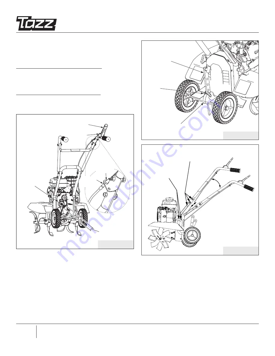
FIGURE 13
BEEHIVE
SPRING
Z-BEND
LINKAGE
DRIVE SAFETY CONTROL
LEVER DISENGAGED
1/8” - 1/4”
STRETCH
LOWER
JAM NUT
UPPER
JAM NUT
FIGURE 14
DRAG
STAKE
LOCK
PIN
DRAG
STAKE
MOUNT
FIGURE 15
HEIGHT ADJUSTMENTS
Handlebar height can be adjusted in two ways to accommo-
date a total of four possible user heights. SEE FIGURE 15.
To adjust height at handlebars do as follows:
1. Remove left and right handlebar mount hardware.
2. Align handlebar at desired height and attach hardware.
To adjust height at pulley box do as follows:
1. Remove hand knob bolts from box and rotate handlebars
to desired height then reattach hand knob bolts.
PULLEY BOX
MOUNT HOLES
(2 POSITIONS)
HANDLEBAR
ADJUSTMENT HOLES
(2 POSITIONS)
HIGHEST
POSITION
LOWEST
POSITION


