Model LR-26C, LR-623, LR-28A, & LR-2355 Hoist Installation and Operation Manual
Stock No. 036268
Page 13 of 27
11.
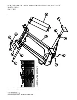
Position a lifting shaft sub-assembly and flats next to each channel long beam. Refer to figure
7. Slide each of the lifting shafts all the way against the inside of the long beam. Push the
hoist so that the oval saddle tube is slid as far rearward as possible (see Figure 4). Weld the
lifting shaft angles to secure the shaft to the long beam as shown in Figure 7. With the shaft
secured, slide the lock collars against the hoist lifting tube and lock them there by tightening
the setscrew (see Figure 5 and 7). Torque the setscrew to 24 ft-lb.
/,)7,1*6+$)7
68%$66(0%/<
6758&785$/&+$11(/
/21*6,//
[
[)/$7
+2,67
6$''/(
+2,6772%2'<$77$&+0(17'(7$,/)256758&785$/&+$11(//21*6,//
$1'02817,1*+(,*+7
/,)7,1*6+$)7
68%$66(0%/<
6758&785$/&+$11(/
/21*6,//
[
[)/$7
+2,67
6$''/(
+2,6772%2'<$77$&+0(17'(7$,/)256758&785$/&+$11(//21*6,//
$1'02817,1*+(,*+7
FIGURE 7


