TBS Installation Manual
–
3D FLASH+
TBS 3D FLASH+ Mounting and Installation Guideline
•
TBS-061
•
Rev 11-2023
page 8 of 17
3.5
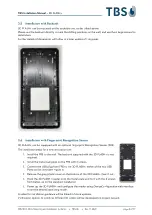
Installation with Backunit
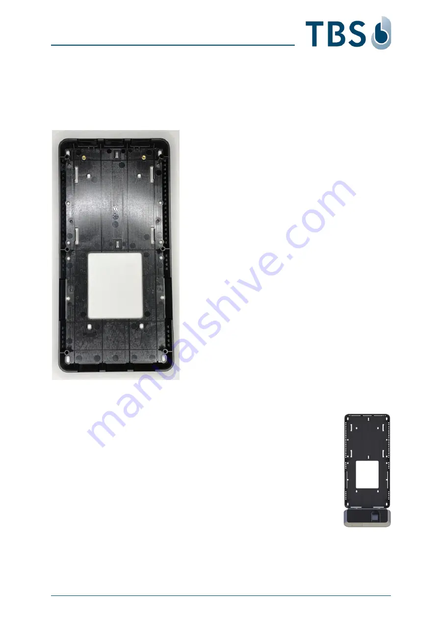
3D FLASH+ can be mounted on the backside unit, as described above.
Please use the backunit directly to mark the drilling positions on the wall, and use the 6 large screws for
installation.
Further details of dimensions will follow in a later update of this guide.
3.6
Installation with Fingerprint Recognition Sensor
3D FLASH+ can be equipped with an optional Fingerprint Recognition Sensor (FRS).
The installation steps for a new installation are:
1.
Install the FRS to the wall. The backunit supplied with the 3D FLASH+ is not
required.
2.
Install the metal wall plate on the FRS with 6 screws.
3.
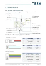
Connect the USB plug from FRS to the 3D FLASH+, either of the two USB
Ports can be used (see Figure 5).
4.
Remove the grey plastic cover on the bottom of the 3D FLASH+ (tear it out).
5.
Hook the 3D FLASH+ reader onto the metal plate and fix it with the 2 screws
from below, as on the standard installation.
6.
Power up the 3D FLASH+ and configure the reader using
DeviceConfiguration
web interface
to set the desired operating mode.
A video for installation guidance will be linked in future updates.
Verification options to combine different ID factors will be developed on project request.


