


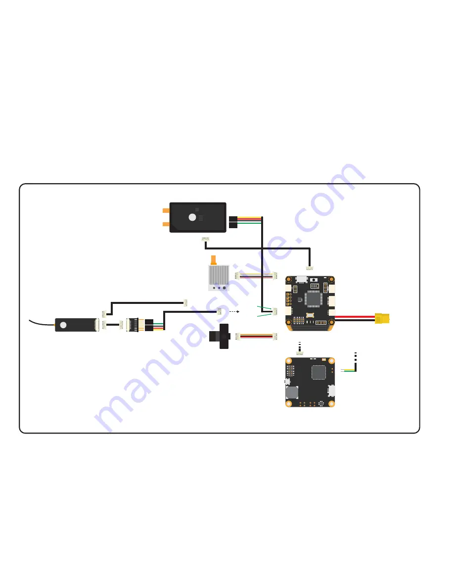
Connecting CRSF from TBS CROSSFIRE RX to TBS POWERCUBE FC
Pilot Camera
Video Transmitter
May 2017 - by ivc.no/tbs
CH 1 + -
CH 2 + -
CH 3 + -
CH 4 + -
CH 5 + -
CH 6 + -
CH 7 + -
CH 8 + -
ANT 1 ANT 2
TRB CR
OSSFIRE
true c
onnec
tivit
y
Bind
B-LiPo
Status
USB BST
TBS CROSSFIRE
DIVERSITY Receiver
Colibri R V2
boot
UART1
BUZZER
RX
GPS/Mag/Alt
LED_Strip
U + -
U + -
Servo
+
++
-
-
USB
DCDC PWR STAT
SWD
XT60
TBS POWERCUBE
BST cable to be able to get
CORE PRO telemetry and control
the OSD using the radio sticks.
Connect to
bottom layer
CH 7 (RX) from UART1 TX
CH8 (TX) to UART1 RX,
+5V, GND
CROSSFIRE DIVERSITY to COLIBRI FC cable, plugs
into UART1 port on FC:
• Servo header #1 on CH 7 (signal pin only):
- Pin 1 - Crossfire output 7 RX from FC UART1 TX
• Servo header #2 on CH 8:
- Pin 1 - Crossfire output 8 TX to FC UART1 RX
- Pin 2 - Servo rail to FC +5V
- Pin 3 - Servo header GND to FC GND
CROSSFIRE DIVERSITY TX configuration:
Under receiver settings, map output 7 to “CRSF
RX” and output 8 to “CRSF TX”.
The bi-directional serial communication carries
R/C control signal, no need for R/C IN connection.
LED2
4
1
Pin-out:
UART1 RX
UART1 TX
GND
4.7V/+5V
+
-
-
+
LED2
LED1
UART2
RX
UART2
TX
TBS PNP PRO V2
DIGITAL CUR. SENSOR
UNIFY PRO INTEGRATED
CAM SWITCH
DCDC 5V, DCDC12V
TBS FPVision
Pin-out:
UART2 RX
UART2 TX
CROSSFIRE RX
will get +5V and
GND from BST line
(also supplying servo
connectors).
Note: The TBS PDB will
not power the BST line,
only FPVision.
FPVision alt.:
If you use the FPVision
layer, you can decide
if you want to use UART2
on the FPVision (which is
routed to COLIBRI FC
through the stacking
header).
CH4
CH3
CH2
CH1
5V
GND
TBS CROSSFIRE
micro receiver
TBS CROSSFIRE MICRO V2
CROSSFIRE MICRO to COLIBRI FC cable, plugs
into UART1 port on FC:
• Servo header #1 on CH 2 (signal pin only):
- Pin 1 - Crossfire output 2 RX from FC UART1 TX
• Servo header #2 on CH 1:
- Pin 1 - Crossfire output 1 TX to FC UART1 RX
- Pin 2 - Servo rail to FC +5V
- Pin 3 - Servo header GND to FC GND
CROSSFIRE MICRO TX configuration:
Under receiver settings, map output 2 to “CRSF
RX” and output 1 to “CRSF TX”.
CH2 (RX) from
UART1 TX (Green)
CH1 (TX) to UART1 RX (Yellow),
+5V (Red), GND (Black)
BST cable to be able to get
CORE PRO telemetry and control
the OSD using the radio sticks.
Or
GND
5V
CH2
GND
5V
CH1


