- 5 -
TC1631R/S
User's Manual
Rev. 1.6
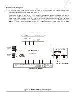
LEDs Functions
Alarm-
ALM:
Alarm indicator. The Alarm LED will flash when following conditions occur:
The unit is in a diagnostic mode.
When an invalid line code or line length is set.
Optic signal is lost.
Local T1/E1 signal is lost or all ones signal is received from customer's device.
Remote T1/E1 signal is lost.
When the "Line Distance" setting is set as "0 0 1" or "0 1 0" (with internal SW2-6, 7, and 8).
Power Supply Status-
Power A/B:
These LEDs indicate which power source on the rear panel the unit is drawing from. If power redundancy is
utilized, both LEDs will be lit.
Vcc:
+5V Voltage indicator. This LED should light whenever power is connected to the unit. It indicates the
correct operating voltage is being derived from the power source.
Optic Signal Status-
Rx-A:
Solidly lit, it indicates optic received "OK" from primary side ("A" side).
Flashes when the optical signal at Rx-A is lost.
Rx-B:
Solidly lit, it indicates optic received "OK" from secondary side ("B" side).
Flashes when the optical signal at Rx-B is lost or "B" side is not enabled.
USE-B:
Solidly lit, it indicates secondary optic signal is being used due to primary optic signal lost.
"Off" when secondary optic receiver is not enabled or primary optic signal is being used.
Note: Only when Optional Optical Redundancy is ordered on the units. Secondary side ("B" side) is optional.
SYNC:
Solidly lit, it indicates a valid composite signal is being received.
Flashes when the optical signal is lost.
Configuration Setting-
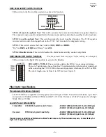
LEN:
Copper Line Length indicator. "Off" whenever the minimum T1 Line Length is set to "0-133 feet" (factory
default setting) or zero "0" for the E1 interface.
Solidly lit, when the T1 Line Length is set to any of the following lengths "134-266," "267-399," "400-533,"
or "534-655" feet, using the internal (SW2-6, 7 and 8) dip switches. (see Configuration Table - page 10).
See
Important Note on page 2 before doing any changes.
Local T1/E1 status and warning-
LOCRD:
Local Receive Data. Solidly lit, it indicates the T1/E1 signal is received from local user's equipment.
Flashes when the T1/E1 signal is lost from local user's equipment.
LAIS:
Local All Ones. When flashing, it indicates "all ones" signal received from user's equipment.
BPV:
Bipolar Violations. This LED will flash when bipolar violations (Line Code violations) are detected or the
Line Length setting is invalid.
LOCLB:
Local Loopback. When lit, it indicates that the LOCLB function is enabled (SW1-2 is On).
Remote T1/E1 status and warning-
RMTRD:
Remote Receive Data. Solidly lit, it indicates the T1/E1 signal is received from remote user's equipment.
Flashes when the T1/E1 signal is lost from remote user's equipment.
RAIS:
Remote All Ones. When flashing, it indicates "all ones" signal received at the remote TC1631 unit.
RMTLB:
Remote Loopback. When lit, it indicates that the RMTLB function is enabled (local SW1-1 is On).
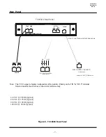
Front Panel
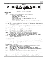
Figure 2. TC1631R/S's Front Panel
T1/E1 FIBER OPTIC MODEM
RxA
RxB
TxA
TxB
TCCOMM.COM
Made in U.S.A.
1
2
3 4
O N
1 2 3 4
AMI
B8ZS/HDB3
DISALM
RMTLB
LOCLB
RMTRD
RAIS
RMTLB
LEN
LOCRD
LAIS
LOCLB
BPV
Rx-A
Rx-B
USE-B
SYNC
ALM
PWRA
PWRB
Vcc


