- 8 -
TC1631R/S
User's Manual
Rev. 1.6
Functional Description
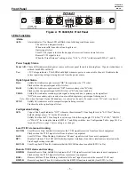
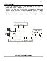
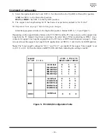
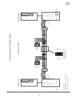
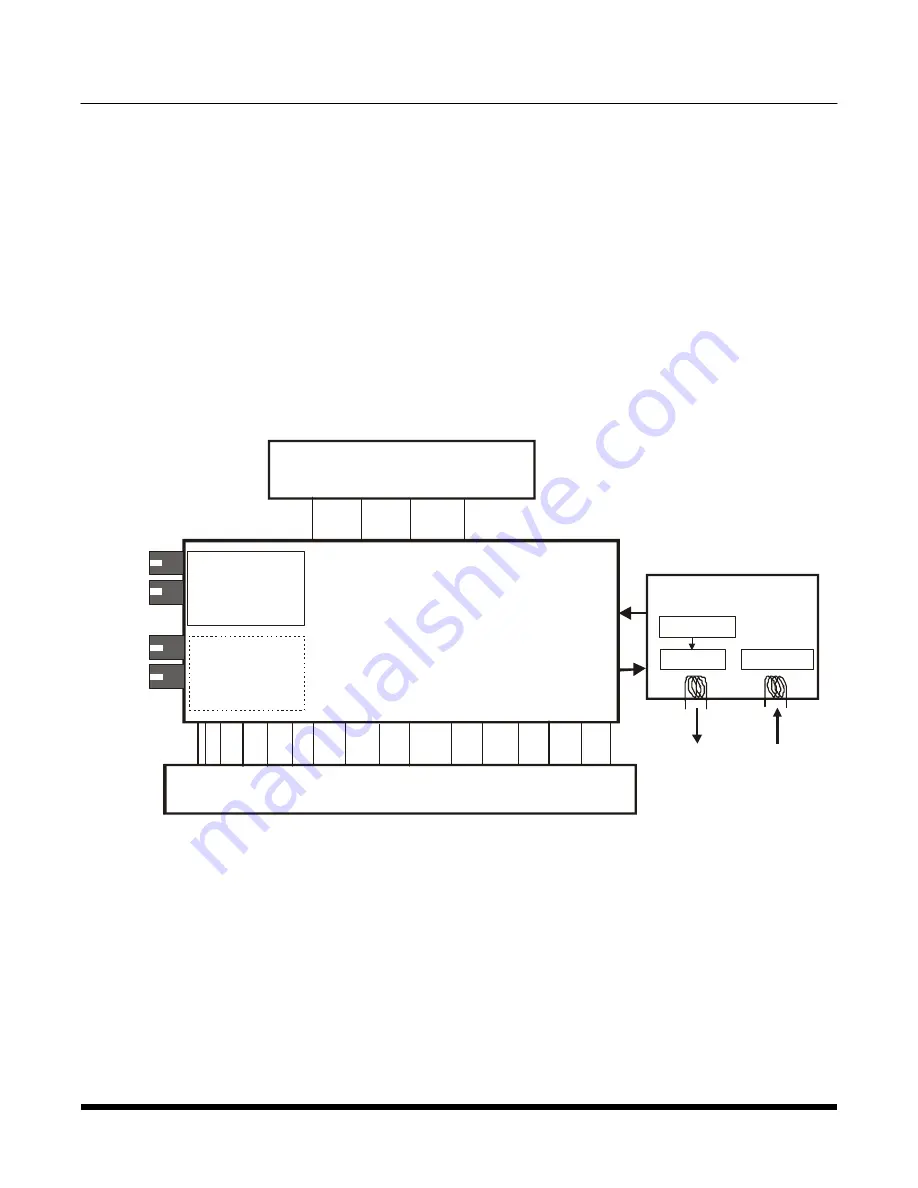
As shown in figure 4, the TC1631 consists of five basic function blocks: DIP switches, LEDs, T1/E1
interface, T1/E1 signal processor and optic interface.
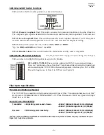
DIP switches are used to configure the TC1631 according to a customer's application such as line code and
line distances. LEDs are used to display corresponding DIP switches settings, power supply status, optic
signal status, signal warnings, alarm, etc... the T1/E1 interface converts T1/E1 analog signals to digital
signals and provides local and remote loopback function. The signal processor composes T1/E1's timing and
data to a bit stream. The optic interface converts the electrical bit stream to an optic signal and vice versa.
Figure 4. TC1631R/S Functional Diagram
T1/E1 Signal Processor
Optic interface
(Optical
Redundant
Models Only)
AMI or
B8ZS/HDB3
Disable
Alarm
Remote
Loop
Test
LED Indicators on front panel
to optic
cable
to optic
cable
Replaceable T1/E1
line Interface Module
Elastic Buffer
to T1/E1 line
from T1/E1 line
Line Driver
Line Receiver
TC1631R/S
External DIP Switches (accessible from front panel)
TxA
TxB
RxA
RxB
Local
Loop
Test
Power
A,B
Vcc Alarm
SYNC
Rx-B USE-B
Rx-A
RMTRD LOCRD
Local
Loop
back
Remote
Loop
back
Local All
Ones
Warning
Remote
All Ones
Warning
Bipolar
Violation
Line
length
Setting


