- 22 -
TC2200R/S Bus
User's Manual
Rev. 2.2
Appendix A - DB25 to 2 RJ-11’s Adapter
Description
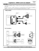
If using the optional DB25 to 2 RJ-11’s Adapter, refer to the diagrams below for proper installation and pin
connections.
The DB25 to 2 RJ-11’s Adapter, separates the two independent RS-232 data channels on the DB25F.
Channel 1 is made of pins (2, 3, and 7) while Channels 2 is made of pins (4, 5, and 7).
Figure 22. DB25 Cable Assembly and Virtual Pin Connections Diagrams
ADAPTER’S
RJ-11 PLUG’s
DCE
Pin Connections
Cable Assembly
To RTU/PLC
To TC1900
TC2200
To TC1900
To RTU/PLC
RJ-11 JACK
pin assignment
DB25 MALE
Connector
Channel 1
Channel 2
DB25 MALE
Connector
TC1900
DB25 MALE
Connector
RJ-11 to
DB25 Connector
DB25 to RJ-11
ADAPTER
RJ-11
Cross-Over
Cable
RJ-11
3
TxD
RxD
RTS
RxD
TxD
CTS
GND
GND
GND
5
7
7
2
4
1
6
6
6
2
5
5
4
3
4
4
5
4
3
3
5
2
2
6
1
1
Tx Data
Rx Data
Ground
6
6
7
5
5
4
4
3
3
2
2
1
1
TC
C
O
M
M
.C
O
M
C
H
2
C
H
1
TC
AD
-2
5M
-2
-1
1F


