TC3006
(LED/ELED/LASER)
User's Manual
Rev. 1.8
-6-
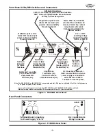
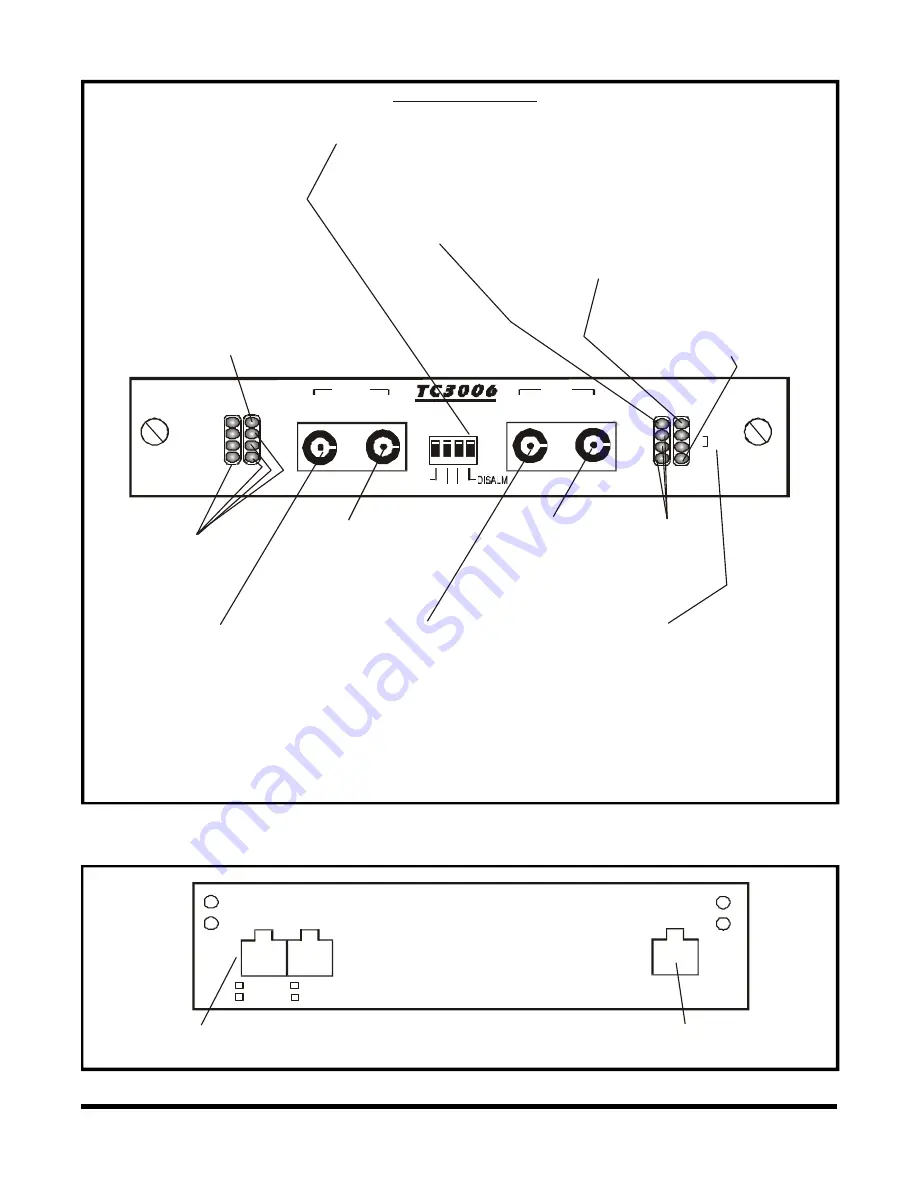
Front Panel LEDs, DIP Switches and Connectors
Figure 2. TC3006's Rear Panel
Figure 1. TC3006's Front Panel
Rear Panel Connectors
+ -
+ -
12VDC
48VDC
24VDC
125VDC
ALARM
PWR
A
PWR
B
Terminal Block Connectors
for Power Supply "A" & "B"
Dry Contact Alarm
Relay Connector
1
2
3
4
ON
Single Mode
Transmitter (Tx):
Connect to remote
unit's SM Receiver (Rx).
Note: The MM RX/SM RX or (SM RX/SM RX - on repeater models) LEDs may be arbitrarily Lit or Off on initial power up
(or if power is cycled). This is normal.
Once a valid optical signal is received, the will be solidly lit.
If the optical signal is then removed the LEDs mentioned will turn Off. (Normal condition)
MM RX/SM RX or (SM RX/SM RX) LEDs
Multimode Transmitter
(Tx): Connect to local
equipment's MM
Receiver (Rx).
Not Used.
Reserved
for future
functions.
Not Used.
Reserved
for future
functions.
Single Mode
Receiver (Rx):
Connect to
remote unit's SM
Transmitter (Tx).
Multimode
Receiver (Rx):
Connect to local
equipment's MM
Transmitter (Tx).
Multimode optic receive
status: MM received optic
power is above sensitivity
threshold when lit.
Single Mode optic receive
status: SM received optic
power is above sensitivity
threshold when lit.
Alarm: When lit, it indicates
a broken fiber condition and
closure of alarm dry contact
relay (buzzer will sound).
Buzzer can be disabled by
"DISALM” switch.
DIP Switch Functions
SW1,2,3 - Not Used; reserved for future functions.
SW4 - Down (or Right) Disables the audio buzzer
and Dry Contact Relay Alarm.
Vcc: +5 VDC
operating voltage
derived from either
PWR A or PWR B
Made in U.S.A.
Vcc
SM RX
B
A
MM RX
TCCOMM.COM
ALM
PWR
GIGABIT ETHERNET
FIBER OPTIC
MODE CONVERTER
Rx
Tx
Rx
Tx
SM
MM
DC Power Input Status for
PWR A and/or PWR B: Lit when
power supply is connected to
either PWR A or PWR B
connector on the rear panel


