TC8619 Rev 1.1 User Manual
B-1
Appendix B
Push Button & LED Functions
B.1
CLEAR ERROR Button Description
The recent enhancements implemented on the TC8619 (Ethernet over T1/E1) will
make troubleshooting a much easier process. The alarm LEDs - BPV, CRC, and
SYNC - can now latch abnormal conditions until they are reset by the user. These
functions are realized in part by the newly added CLEAR ERROR push button.
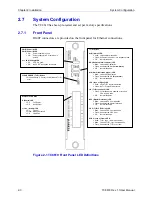
Figure B-1 Front Panel CLEAR ERROR push button
B.1.1
CLEAR ERROR Push Button Functions
1.
To reset the local unit's alarm LEDs, hold down the “CLEAR ERROR” button
for at least 3 seconds until you see the alarm LEDs flash in sequence.
B.2
LED Functions
RMT
: displays the remote unit's LED status on the local unit
BPV
: displays bi-polar violation(s) for the ingress T1/E1 signal
CRC
: displays error(s) in data integrity (only for T1/E1 ESF frame and E1 built-in
CRC)
SYNC
: displays frame locking for T1/E1 (ESF framing) or E1 (PCM31C framing)
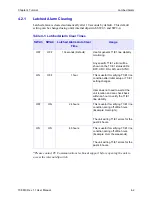
The alarm LEDs - BPV, CRC and SYNC - all have a latching functionality to
indicate the number of occurrences for each error. These LEDs will continuously
flash at regular intervals until reset by the user. The behavior is noted here:
•
When an LED blinks once, it indicates a single error has occurred once. When
an LED blinks twice, it indicates the error has occurred twice. When the LED
blinks 3 times, it indicates the error has occurred 3 or more times.

