31
MODIFIERS
Modifier
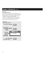
To connect a Modifier to a parameter, dial the Parameter wheel to
select a parameter, and the Value wheel to select a Modifier. Dial
the Value wheel fully counter clockwise to remove a connection.
If you want to remove all links from the Matrix, press
Exit twice and you will see a pop up box asking you to
confirm with Enter or abort with Exit.
Place the cursor at an unconnected parameter and press
Enter to access the Editing of current parameter directly.
Press Exit to get back to the Modifier Matrix.
Each modifier can be connected to several parameters at the
same time but each parameter can have only one source.
The maximum number of connections that can be made in the
Matrix is 20.
Press Enter while the cursor is pointing to a connected
parameter, and discover the Link display.
Modifiers controlling Modifiers
The parameters for the Internal Modifiers are located at the very
end of the Parameter list, e.g. this makes it possible to control
Modifiers via Modifiers. That enables you to trigger the ADSR’s,
the Freeform Modifier etc., via the External Modifiers.
NOTE: A Modifier cannot be connected to it’s own parameters.
The Link page
When you have a Modifier connected to a parameter, (e.g. the
Alpha Mod. connected to the Panner speed) it is possible to make
a transformation between the Modifier output and the parameter
input. Move the cursor to connect in the Matrix by dialing the
Parameter wheel and press Enter to get to the Link display.
In the Link display, you can change the transition between the
Modifier and the actual movement of the current parameter.
An active transformation will occur as a small square on the
connection between a Modifier and a parameter.
Low input
Sets the value that the controlled parameter will have when the
Modifier is in minimum position.
Mid input
Sets the value that the controlled parameter will have when the
Modifier is in middle position.
High input
Sets the value that the controlled parameter will have when the
Modifier is in maximum position.
NOTE: These same parameters also apply to the other
modulation sources, for example Envelope, Low when the input
signal into the FireworX is at its lowest and High when it is at its
loudest.
Slope
Dial the Slope parameter to change the shape of the curve. Try it
out and watch the curve change.
Glide time
With this parameter you can set a minimum time that the
parameter should use to go from maximum to minimum or vice
versa, meaning that even though you move an expression pedal
from min. to max. in a split second, the current parameter will
still take some time to go through the same range.
This will also smooth out a Modifier movement e.g. when
connected to a pitch voice, instead of stepping through the pitch
values, FireworX will be sliding through.
Press Exit to leave the Link display.
Default parameter setting
The default setting of a Matrix connected parameter at Recall is
equal to its setting in the Edit parameter display.
Example: The Reverb mix level is set up to be controlled by a
MIDI controller, and the Mix parameter in the Edit parameter
display is set to 15%. When this Preset is Recalled, the Reverb
Mix will be 15%, and at first movement of the MIDI controller,
you will be in total control of the parameter.
The Dials page
Press the Mod key and use the < > Arrow keys to select the Dials
(see picture on page 31).
In the Dial page it is possible to simulate any two of the eight
External controllers using the Parameter and Value wheel. By
dialing, you can test if the links in the Matrix are responding
correctly without having any external device connected.
If you want to make sure that the external input jack is
calibrated correctly, you can test it by watching the
Dials while moving the external device from 0-100%.
Summary of Contents for FirewarX
Page 1: ...FireworX STUDIO EFFECTS PROCESSOR USERS MANUAL ...
Page 2: ......


