background image

______________________________________________________________________________________________________________________________________________________________________________

_________________ 

TC Electronic A/S 

Gold Channel Service manual 

page 3 

Introduction 


The purpose of this manual is to support skilled technicians in repairing the     Gold 
Channel. 

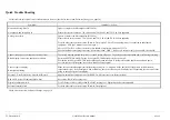
The manual begins with a Quick Trouble Shooting table. Here, hints, advices and 
possible problems are described. 

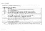
If the problem is more serious, the next step is to use the Built-in Test Program. 
With this program the problem can often be narrowed down to a specific section, 
channel or even component. 

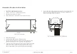
The next section consist of disassembly and exchange procedures. Please be aware 
of warranty rights before disassembling. Refer to the warranty card. 

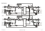
The Block diagram gives a quick overview of the signal flow. 

Circuit description is a brief description of the circuits on the different boards.  

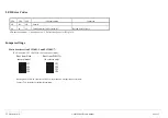
LED error codes and Jumper settings are described on page 13. 

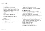
Software Changes describes the changes from older software versions to newer 
versions. 

Appendix contains Schematics, Part lists, PCB Layouts and service notes. 

The schematics start with a main sheet, where sub sheets are shown as blocks. 
Even sub sheets might have sub sheets. In the schematics some connections have 
label names to help the reader. If a label name is framed, it means that it is 
"connected" to another sheet. Label names followed by the symbol "*" mean that 
the signal is active low, i.e. RESET*: the reset function takes place when the signal 
is low.  

Part lists contain a column called TCcode/ Item no. Use this code/no. when 
ordering spare parts. If the field is empty; it means the component cannot be 
ordered separately. 
The coordinates in the column Pos. refer to the PCB layout page. The column 
named Page refers to page no. in the schematics. In column comments a short 
explanation of the function is stated. For some components, alternative types are 
mentioned. 

Some PCB layouts are made as gatefolds (fold-out page). 

Finally appendix contains a list for mechanical parts. 

This service manual does not contain schematics for the power supply module, 
because any attempt to repair the power supply module must be completed with 
some safety tests such as high voltage and EMC tests. Hence, it is strongly 
recommended that the entire power supply module is replaced in case of 
malfunction. 


Summary of Contents for Gold Channel

Page 1: ......

Page 2: ...6 Built in Test Program 7 Disassembly Procedure for Main Board 8 Disassembly Procedure for Front Section 9 Exchange of Power Supply Module 10 Exchange of Battery Exchange procedure 11 Block Diagram 1...

Page 3: ...ppendix contains Schematics Part lists PCB Layouts and service notes The schematics start with a main sheet where sub sheets are shown as blocks Even sub sheets might have sub sheets In the schematics...

Page 4: ..._______________________________________________________________________________________________________________________________________________________ _________________ TC Electronic A S Gold Channel...

Page 5: ...it is also OK Cannot turn power off with power switch at front The switch must be pressed for at least 1 second to turn off power The delay provide unintended power off during recording Blank display...

Page 6: ...6 Software Boot Menu To access the Software Boot Menu press the ENTER button while powering on Option Description Load PCMCIA Load Application or Boot software directly from PCMCIA card Load Link Not...

Page 7: ...d on both analog outputs When connected to one of the analog inputs the display reads OK if the level is correct In this way a problem might be narrowed down to a specific input or output The levels c...

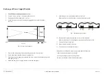
Page 8: ...ut connector see fig 3 7 Remove the screws at the ADAT in out connector see fig 3 8 Remove the jack nut at the EXT IN connector see fig 3 7 Push the main board into the front profile a little to free...

Page 9: ...nels 5 Remove the front section 6 Pull off the PARAMETER and VALUE knobs by hand 7 Place the front profile horizontally with the buttons facing down Place the profile on some stand off to avoid any pr...

Page 10: ...ower supply by removing the screw just below the mains plug at the back panel see fig 6 8 Mount the new power supply with the screw at the back panel 8 Solder the power wires into the main board see f...

Page 11: ...solder the terminals one by one Avoid any short circuit of the terminals 5 The voltage measured directly across the terminals of the new battery should be higher than 3 0VDC 6 Do not discard the old b...

Page 12: ..._______________________________________________________________________________________________________________________________________________ __________________ TC Electronic A S Gold Channel Servic...

Page 13: ...________________________________________________________________________________________________________________________ __________________ TC Electronic A S Gold Channel Service manual page 13 Fig 8...

Page 14: ...rate this frequency is divided down to 64 x sample rate and to 1 x sample rate by the DARC The PLL has its own power regulation Analog section is placed mainly on the right side of the main board The...

Page 15: ...n Comment off off off Normal on on on Checksum error in boot software Reload boot software LD4 has two functions 1 Show power on 2 Define clean power for IC33 pin16 Jumper settings Main board version...

Page 16: ...ixed Software changes from 1 03 to 1 04 1 POST Insert Can t enter insert edit window fixed 2 EditPage Unlinking with Enter sets channel 2 effect on If it s done with the value dial the effect returns...

Page 17: ...Mode Rejection RS 200 Ohm 60 dB 50 60 Hz 70 dB 1 kHz A to D Conversion 24 bit 1 bit 128 times oversampling A to D Delay 0 8 ms 48 kHz ANALOG OUPUT Connectors XLR balanced pin 2 hot Impedance 40 Ohm A...

Page 18: ...________________________________________________________________ __________________ TC Electronic A S Gold Channel Service manual page 18 Backup Battery Life 10 years Warranty Parts and Labor 1 year N...

Page 19: ...3001 7 2 pages Schematic for Main board ver PC13001 5 14 pages Part list for Main board ver PC13001 5 15 pages PCB lay out for Main board ver PC13001 5 2 pages Schematic for Front boards ver PC12506 2...

Reviews: