background image

39

THE BLOCKS

Large increments of the Pan Center, in

combination with a broad Depth will cause the
Panner to pan beyond a normal stereo image.

Width

(only in Surround Panner)

Controls the Width of the Panner. When Width is set to
more than 100%, the Panner will pan beyond a normal
stereo image. Check it out. 

Mix

Mix between direct sound and effect.

In Level

Controls the input level of the block. 

Out Level

Controls the output level of the block.

Mute mode

See Mute mode in the introduction of this chapter.

The Pitch block

In the Pitch block there are two basic Pitch types:
Fixed and Intelligent. The difference between the two
types is that while the Intelligent pitcher is capable of
staying inside a certain key and scale, the Fixed pitch
will always add the exact same amount of pitch no
matter the input signal. 
The Detune algorithm is used for smaller amounts of
pitch, to create doubling sounds.
The optimal pitch detection is acheived by placing the
Pitch block as close to the Input section as possible. It
is very important to be in tune when playing with the
Intelligent pitcher. Use the Tuner for that purpose.

INTELLIGENT PITCHER

Key

With this parameter you are able to tell the G-Force
which key you are playing in. This is very important
information, because the voices of the intelligent
pitcher are generated from it.

Scale

Sets the scale that the Intelligent Pitcher uses,
meaning that the voices from the G-Force will be within
this current scale. It is recommended that this scale be
equal to the scale you are playing, otherwise you might
get some very strange voicings.

Mode

Choose the mode of the Intelligent Pitcher.
Stepped: The Pitcher will only play notes within the
current scale and key no matter what you play. 
Smooth: The Pitcher will follow the incoming signal.
This means that you can bend a tone, and the Pitcher
will bend with you.

Voice 1-2

Sets the step in the current scale and key in which you
want the pitcher to play.
Example: You want the G-Force to play the third step
in C-Major. Set the Key to C, and the Scale to Ionian
Major. Now set Voice 1 to step 3. No matter what you
play within C-Major the G-Force will now
play/transpose two steps further up the scale, i.e. if you
play a C now, the G-Force will play an E which is the
third step of C-Major.
Max. pitch is +/- one octave.

Detune Voice 1-2

Adjusts the detune of the two Voices. By connecting an
LFO to these parameters you can add a vibrato to the
pitch voices.

Delay 1-2

Sets the Delay of the each of the two voices. Max.
delay time per voice is 400 ms.

Pan Position 1-2

Controls the panning of each of the two pitch voices. 

Summary of Contents for GUITAR

Page 1: ...G Force GUITAR EFFECTS PROCESSOR USER S MANUAL...

Page 2: ......

Page 3: ...ipment should be installed near the socket outlet and disconnection of the device should be easily accessible To completely disconnect from AC mains disconnect the power supply cord from the AC recept...

Page 4: ...to part 15 of the FCC rules These limits are designed to provide reasonable protection against harmful interference in residential installations This equipment generates uses and can radiate radio fre...

Page 5: ...bout this Manual Foreword by Palle Schultz Buttons Knobs Controllers and other functions Inputs Outputs build a User Preset connect the Modifiers setup an Expression Pedal etc Recalling a Preset Facto...

Page 6: ......

Page 7: ...e Check out the Modifier Matrix and discover a powerful tool for real time external and internal control of the many parameters of the G Force About this Manual Many people in the music business and e...

Page 8: ...for my guitar From simple use of standard effects like delay chorus and reverb connected in a straight line I now find myself thinking up a non existing effect like say a tremolo that only kicks in w...

Page 9: ...ting up your MIDI board Press I O Setup and select MIDI using the Arrow keys Adjust the MIDI basic channel so it matches the one of your foot controller Be sure that Program Change is enabled Your foo...

Page 10: ...an write into the G Force refer to Billboard in the Utility section Both Tuner and Tempo use the Billboard to display information as well Beneath the Billboard you will find four indicators displaying...

Page 11: ...can select different menus by pressing the Arrow keys i e in the Effects display you can select between Mix Edit Routing and Layout THE PARAMETER WHEEL Use the Parameter wheel to change posi tion of...

Page 12: ...ou are connecting the Outputs via stereo jacks to unbalanced equipment you must tie ring and sleeve together in the cable ends away from the G Force You can always use standard mono guitar cables to c...

Page 13: ...tal inputs The Input level of the G Force automatically optimizes the signal to noise ratio via a small relay in the input section You will see a prompt on the display and may hear a small click when...

Page 14: ...preset There are a couple of different ways to set the level of a preset but in any case you should consider reserving a bit of headroom for the preset you want to be the loudest One method is to low...

Page 15: ...the Value wheel and press Enter to select a letter When you finish the name go to Done using the Value wheel and press Enter to Store How to obtain spillover at preset change Spillover from one prese...

Page 16: ...ght external pedals or MIDI controllers Connecting Your Expression pedal can be connected in two ways either directly to the External control jack on the back panel of the G Force or via a MIDI board...

Page 17: ...ibility of performing MIDI on off functions MIDI bypass etc The G Force has a list of board defaults that makes it possible to setup these boards really fast These are the boards in the list ADA MXC A...

Page 18: ...quipment Input Output Set the Input level of the G Force using the In knob in the upper left corner of the front panel To get maximum quality from the 24 bit AD converter the input meter should show a...

Page 19: ...elay block in the second preset NOTE Changing parameters like the Feedback or Mix over a preset change can kill the Delay Optimal preset change Since the change from one preset to another can contain...

Page 20: ...name of the preset to Store dial the Parameter wheel You are now able to write a new name using the Letterbox Simply dial the Value wheel and press Enter to select new letters or numbers Select CAP b...

Page 21: ...h block Set In Level in each block Selected Select Out and press Enter to edit Speaker filters Dial Parameter wheel to select effect and press Enter to edit right away Double click on the block bypass...

Page 22: ...ress the Effects key In the header of the effects display you can choose between Mix Edit Routing and Layout By using the Arrow keys you can step between the four displays If an effect is bypassed it...

Page 23: ...ut level adjusted with the front panel controls Output level adjusted with the front panel controls and the Digital input sample rate shown only when you are using the digital input Note The input lev...

Page 24: ...ternal MIDI device via controller 0 Coarse plus a sent program change according to the following table Bank Size must be set to 100 and the Fine Coarse parameter must be set according to the sending d...

Page 25: ...essages for exactly this purpose If you do not own a board with these features you can use an ordinary program change to bypass a block e g You can setup the Pan section to be bypassed when you send o...

Page 26: ...to it s setting in the Edit parameter display Example The Reverb mix level is set up to be controlled by a pedal and the Mix parameter in the Edit parameter display is set to 15 When this preset is R...

Page 27: ...oint Parameter List The Matrix is where you connect your External pedals set up in I O Setup Ext Input or the internal Modifiers to the parameters you want to control Dial the Parameter wheel to move...

Page 28: ...for a 7 string guitar The G Force responds to notes as low as A However the precision in such a low range may vary depending on your type of guitar setup 4s Bass D E Matches the range of a 4 string b...

Page 29: ...sequence for as long as the signal stays above threshold Loop Retrig Will keep running the ADSR sequence for as long as the signal stays above threshold but are capable of retriggering MODIFIER durin...

Page 30: ...uch as memory protect backup of the User bank etc Display Viewing Angle Adjust for best contrast of the LCD display Parameter dial direction FWD UP DOWN Select what direction the parameter wheel shoul...

Page 31: ...EXIT to leave the Pedal Curve display The Pedal Curve parameter is global and is therefore not changed with presets Tuner MIDI Out In the Utility menu a Tuner MIDI Out parameter is added This paramet...

Page 32: ...the global message Select DONE and press Enter to finalize UTILITY Billboard Speed Activity Preset change Always show tuner Run message Edit message Message string Activity Scrolling 30 Billboard In...

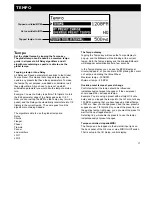
Page 33: ...Tempo display to pop up and the Billboard will be blinking at the current tempo Both the Tempo display and the blinking Billboard will disappear automatically after a few seconds In the Tempo display...

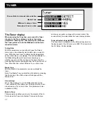
Page 34: ...th the Master tune parameter you can calibrate the tuner Note The Master Tune controls the pitch detector meaning that the tuning of the Pitch voices will change with the Master tune Show always When...

Page 35: ...an that no signal passes through the current block when bypassed 33 THE BLOCKS Gate The basic idea about a Gate is that when the input signal falls below a threshold set up by you the Gate turns down...

Page 36: ...ack to no gain reduction The Compressor in the G Force comes in both a simple and an advanced version The Compressor uses auto makeup gain This means that the Compressor automatically compensates for...

Page 37: ...n the introduction of this chapter Resonance The Resonance filters are basically a high and low cut filter that can be swept up and down the frequency range When the Resonance Q factor parameter is in...

Page 38: ...as the vowels of human speech The basic idea is that you set three coordinates Start Thru and End in a frequency area and then move your sound up and down the curve you created with the coordinates FO...

Page 39: ...he block Mute mode See Mute mode in the introduction of this chapter Pan Trem block A Panner is basically a change of the level opposite in left and right channels An LFO is connected to these levels...

Page 40: ...anner Speed Controls the speed of the Panner The simple Panner always pans fully left and right Tempo The Tempo parameter sets the relationship to the global Tempo e g if you set it to 1 4T you will g...

Page 41: ...key you are playing in This is very important information because the voices of the intelligent pitcher are generated from it Scale Sets the scale that the Intelligent Pitcher uses meaning that the v...

Page 42: ...f the each of the two voices Maximum delay time per voice is 400 ms Level 1 2 Sets the level of the two pitch voices Pan Position 1 2 Controls the panning of each of the two pitch voices Feedback 1 2...

Page 43: ...ter note triplets of the tapped tempo 1 4 equals the BPM tapped Tempo If you select Ignored the current parameter will use the Preset value and will not be affected by the Global Tempo Feedback Adjust...

Page 44: ...4T you will get quarter note triplets of the tapped tempo 1 4 equals the BPM tapped Tempo If you select Ignored the current parameter will use the Preset value and will not be affected by the Global T...

Page 45: ...he two taps Pan position 1 2 Controls the panning of the two Delay taps Lowcut 1 2 Cuts off frequencies lower than the selected frequency The slope of the filter is 12dB octave Highcut 1 2 Cuts off fr...

Page 46: ...Adjusts the amount of Feedback Pan position Controls the panning of the Delay Lowcut Cuts off frequencies lower than the selected The slope of the filter is 12dB octave Highcut Cuts off frequencies h...

Page 47: ...nput level of the block Out Level Controls the output level of the Delay block Mute mode See Mute mode in the introduction of this chapter The Drive The Drive block The Drive is a post distortion It c...

Page 48: ...gives very small variations in pitch these pitch changes blended with the direct sound gives you the Chorus sound while the modulated signal alone will give you a Pitch modulator also known as Vibrato...

Page 49: ...and Curve Speed The speed of the Chorus also known as Rate Tempo The Tempo parameter sets the relationship to the global Tempo e g if you set it to 1 4T you will get quarter note triplets of the tappe...

Page 50: ...l Chorus uses delays at approximately 10 ms while a Flanger is uses delays at around 5 ms Feedback Controls the amount of feedback in the Flanger Note that this parameter can be negative i e feedback...

Page 51: ...shape in the Master section and choose the combination that you like Then try to change the Color in the Room parameters section to find the tonal balance that suits you You will hear a short spatial...

Page 52: ...haracter set by Color Range 50 Predelay Allows adjustment of the predelay the time until the first reflection appears which is automatically set when choosing the Room size Range 50 Decay level Adjust...

Page 53: ...ix This parameter sets the mix relation between the dry direct and the wet signal If you are using G Force as an insert effect this means that your direct signal goes through the G Force In Level Cont...

Page 54: ...rce simply select this parameter and press Enter to store your default settings Set User Info This function makes it possible to store your name and phone number into the G Force Press Enter to access...

Page 55: ...RCA Type Formats EIAJ CP 340 IEC 958 S PDIF 24 bit Sample Rate 44 1 kHz PCMCIA Interface Connector PCMCIA Type 1 cards Standards PCMCIA 2 0 JEIDA 4 0 Card Format Supports up to 2 MB SRAM Control Inte...

Page 56: ...input but the input selector in I O Setup Audio menu is set to Digital The sound is phasing with your direct signal You are running the G Force in a parallel setup but the killdry function in I O Set...

Page 57: ...Altered Note Number X O True Voice X X Velocity Note ON X X Note OFF X X After Touch Key s X O Ch s X X Pitch Bend X O Control Change 0 127 0 127 Prog Change O O True 0 127 0 127 System Exclusive O Bu...

Page 58: ...l Output to the Digital Input which has to be tested and press Enter The AES EBU output can also be connected to the S PDIF input and vice versa PPM must show 0 dB to pass test Press Exit to leave Dig...

Page 59: ...any stereo setup A Detuned setting producing a doubler effect suitable for any stereo setup A subtle Tremolo preset suitable for any stereo setup Great chorused shimmery doubler delay and reverb simi...

Page 60: ...itar Pedal to toe Spinning guitar A fast Wah Filter into a Chorus and Gate like reverb good for anything funky Pedal to heel lowers Wah Envelope controlled fast downward sliding Wah Filter with slow r...

Page 61: ...Check the tittle need we say more Nice greasy lead Gives you that drive with a loose bottom that you know from older tube amps Good for lead Quacks like a duck thanks to a Wah Wah Brings back the 70...

Page 62: ...d an octave and into Phaser Good leads Pedal to heel Mono guitar signal Pedal to toe Stereo octave up A single block with an all purpose Reverb Room A single block with an all purpose Church Reverb A...

Page 63: ...ingle block with an all purpose Auto Resonance Filter An external LFO controls the Resonance filter A single block with an all purpose Drive A single block with an all purpose Drive A single block wit...

Reviews: