Twin City Fan & Blower Installation and Maintenance Manual: IM-495
Electrical Wiring of Fans
The customer is required to investigate and install equipment
in compliance with all local electrical and safety codes for the
equipment location. Twin City Fan & Blower requires all power
cabling be located away from the rotating impeller and fastened
to the inside of the fan housing. Wiring must be routed away from
the motor to reduce potential contact with hot or greasy surfaces.
When a fan is supplied with an outlet damper, wiring the electrical
supply to the motor requires routing the supply through the damper
housing frame. Knockouts of various sizes are provided in the damper
housing frame to accommodate cable connectors or raceway.
Fan Operation - Safety
For general safety practices for air moving equipment, see AMCA
Catalog 410.
Twin City Fan & Blower has many safety accessories available.
These safety devices include (but are not limited to) inlet and
discharge screens. The use, abuse or non-use of safety devices is
the responsibility of the purchaser.
Facility-related safety conditions include fan accessibility and
location. How easily can non-service personnel access the unit? Is
the fan in a hazardous duty environment? Was the unit ordered for
this duty? Other concerns must also be addressed. All fans should
be powered through switches, which are easily accessible to service
personnel from the fan. Every switch should have the ability to be
“locked-off” by the service person and the key to be retained by
this person to prevent accidental power of the fan while service is
in process.
Operation Check List
Check fan mechanism components:
□ System connections are properly made and tightened.
□ Bearings are properly lubricated.
□ Impeller, drives and fan surfaces are clean and free of debris.
□ Rotate the impeller by hand to verify it has not shifted in transit.
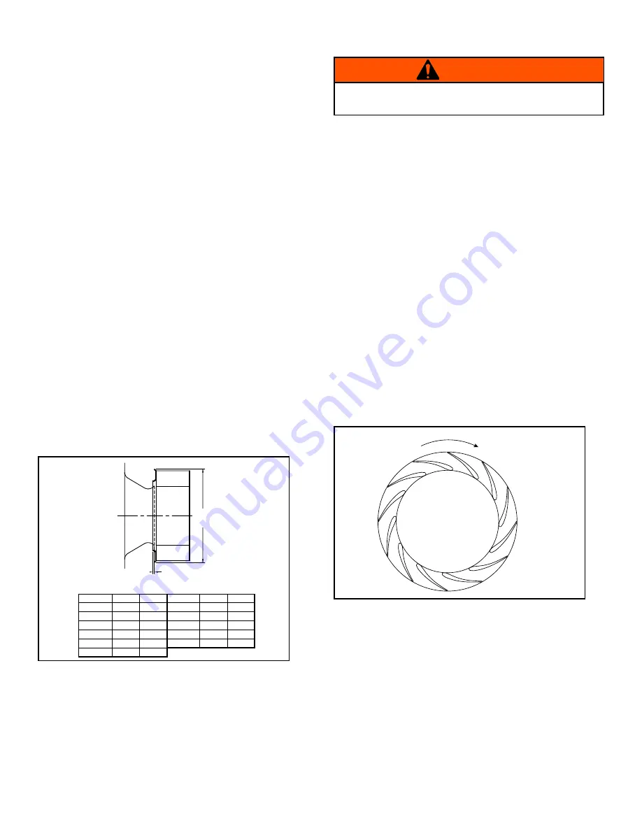
□ Check fan/impeller overlap. (See Figure 4.)
Check fan electrical components:
□ Motor is wired for proper supply voltage.
□ Motor was properly sized for power and rotational inertia of
rotating assembly.
□ Motor is properly grounded.
□ All leads are properly insulated.
Trial “bump”:
□ Turn on power just long enough to start assembly rotating.
□ Check rotation for agreement with rotation arrow.
Does the assembly make any unusual noise? (See Figure 5.)
□ Correct any problems that may have been found.
(Follow safety guidelines - shut power off.) Perform checklist
again until unit is operating properly.
□ Run unit up to speed.
Verify fastener tightness. These may have loosened during
shipment or installation.
□ Set screws attaching impeller hub to shaft.
□ Nuts on inlet funnel.
□ Nuts and bolts holding motor.
□ Nuts holding housing frame to base and base to ground.
□ Bolts in taper-lock bushings.
□ Grease line connections.
After one week of operation, check all nuts, bolts and set screws
and tighten if necessary.
A
DIA
B
Figure 4. Impeller-Funnel Overlap
Size
A
B
Size
A
B
122
12.75
0.130
245/245C
25.51
0.50
150
15.62
0.172
270/270C
28.11
0.55
165
17.18
0.203
300/300C
31.23
0.61
182/182C
19.00
0.38
330/330C
34.36
0.67
200/200C
20.82
0.41
365/365C
38.00
0.75
222/222C
23.16
0.45
MPLFN/MPLFS/MPLQN/MPLQS
Rotation
MPLFN, MPLFS,
MPLQN & MPLQS
Wheels
Figure 5. Proper Impeller Rotation
Verify that proper safety precautions have been followed.
Electrical power must be locked off.
WARNING


