TXP Inst. & Maint. Manual: IM-825
13
Fig. 9: Overview of danger points
1 Inlet flange
2 Fan housing, impeller inside
3 Motor with terminal box, fre-
quency inverter and electrical
connection
4 Outlet opening
Danger zone Description
Inlet flange e Dangers from mov-
ing in
Danger from unex-
pected start-up of
the fan
Danger from rotating
parts
Outlet open-
ing
Danger from ejected
parts
Danger from break-
age
Danger from rotating
parts
Fan housing,
impeller in-
side
Exposure to sharp
edges, corners and
tips
Thermal hazards
Danger zone Description
Danger from rotating
parts
Motor with
terminal box,
frequency in-
verter and
electrical con-
nection
Exposure to electri-
cal energy
Thermal hazards
Fan in gen-
eral
Exposure to noise
Danger from envi-
ronment
Danger due to speed
and resonances
Danger due to
weight and safe
standing
Table 3: Assignment of residual hazards
For more information, see the following
chapters.
2.7.1 Hazards from Fans
Many residual hazards come from the
fan itself and are due to its intended
use. During operation, the impeller ro-
tates inside the fan and this can lead to
risks. As a protective measure against
these risks, the fan has a housing and a
protective grille on the suction side that
prevents the contact of the dangerous
areas. In the case of free-blowing fans,
a protective grille must be added on the
pressure side (available as an acces-
sory). Furthermore, pictograms inform
about potential danger points.
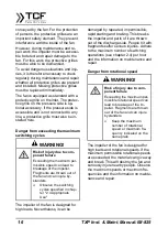
Dangers from moving in
During the operation of the fan, the im-
peller rotates at high speed. The air is
sucked in via the intake port. People


