26
TXP Inst. & Maint. Manual: IM-825
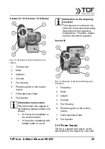
The electrical connection of the IV ver-
sion (terminal box) and the IK version
(frequency converter Kostal) are de-
scribed in this manual. For the connec-
tion of the Omron frequency converter,
refer to the enclosed operating instruc-
tions.
3.3.3 Frequency
The frequency converter converts the
frequency and supply voltage to the fre-
quency and voltage required by the mo-
tor. The requirement for the conversion
of the voltage is that the supply voltage
must be higher or equal to the voltage
required by the motor.
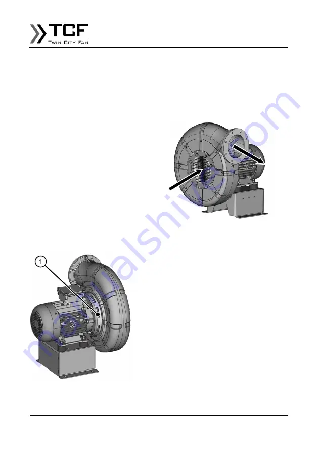
3.3.4 Heat Shield
Some fans are equipped with a heat
shield. This is located on the fan hous-
ing.
The heat shield constructively separates
the motor from the fan housing.
Fig. 14: Heat Shield
1 Heat Shield
Temperatursperre
3.4 Description
The electric motor drives the impeller in-
side the fan. Through the rotating impel-
ler, the fan sucks in the conveying me-
dium (e.g. air) via the intake opening
and transports it to the outlet via the fan
housing.
Fig. 15: Functional description
The fan itself has no controls. It is either
delivered with a frequency inverter or
connected to a separate frequency in-
verter via the terminal box.
3.5 Interfaces
The fan has the following connection el-
ements:
•
Suction Flange
•
Discharge Flange
•
Motor Console
3.6 Modes
General Information
The aerodynamic performance of the
fan can be adapted to the system and
usage requirements during operation via
the speed. The maximum rotational

