38
TXP Inst. & Maint. Manual: IM-825
and on the motor, electrically low-
impedance and permanently con-
nected to protective conductor sys-
tems or the potential equalizing rail.
For this purpose, suitable EMC ca-
ble glands must be used on the mo-
tor side and, if necessary, also on
the INVEOR wall mounting plate.
•
The large-area connection of the
device to the protective conductor
system or the potential equalization
rail must be ensured by one or
more additionally suitable potential
equalizing lines low-impedance and
permanently.
•
The scope of delivery Omron in-
cludes an EMC filter. Instructions
for installation can be found in our
guide.
•
Further information on EMC-compli-
ant installation and installation can
be found in the instructions in the
operating and assembly instructions
of the frequency inverter supplier.
•
When parameterizing customer-
specific frequency inverters, care
must be taken to ensure that the
output voltage on the frequency
converter corresponds to the volt-
age on the motor power plate.
To perform the electrical connection
in the terminal box, proceed as fol-
lows:
•
Make sure that the above points are
true.
•
Insert the electrical connection ca-
ble into the terminal box.
•
Connect the protective conductor
connection in the terminal box to a
suitable protective conductor sys-
tem.
•
Connect the existing temperature
sensor (PTC thermistor or optional
the temperature guard, opener con-
tact) to the converter. The fre-
quency converter must evaluate the
values of the temperature sensor.
•
Perform the electrical connection
according to the diagram in the ter-
minal box.
•
Close unused cable glands in the
terminal box. This prevents dust
and moisture from entering the ter-
minal box.
•
Tighten all contact screws and nuts
to avoid transition resistors. (see
Tab. 7: Tightening Torques for
Threads in Motor terminal Box (IV /
IV & Omron /IV & Kostal))
•
Connect an external frequency in-
verter. Please refer to the manufac-
turer's supplied operating instruc-
tions or the supplied quick guide
•
The electrical connection in the ter-
minal box is complete.
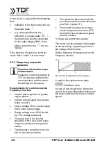
5.5.2.1 Possible Circuits
Circuit
Fig. 25: Triangular circuit

