TXP Inst. & Maint. Manual: IM-825
25
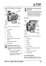
Version IV / IV & Omron / IV & Kostal
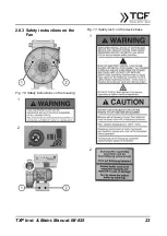
Fig. 12: Structure of the fan (without con-
verter)
1 Terminal box
2 Motor
3 Isolators
4 Console
5 Fan housing
6 Protective grille on the suction
nozzle
7 Outlet opening of fans
8 Fan impeller
Information on execution
This information also applies to
the following design variants (not
shown):
•
IV Omron for installation in
the control cabinet
•
IV Kostal for installation with
adapter plate on a wall
Information on the frequency
converter
The frequency inverters are de-
scribed in the enclosed operating
instructions of the respective
manufacturer. Therefore, please
note the documents supplied.
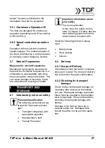
Version IK
Fig. 13: Structure of the fan (with frequency
converter)
1 Frequency
2 Motor
3 Isolator
4 Console
5 Fan Housing
6 Protective grille on the suction
nozzle
7 Outlet opening of fans
8 Fan impeller
3.3.2 Power Supply
The fan is supplied with power via the
terminal box or the frequency converter.

