HGL Manual
5.0 PQconnect Connectivity
19
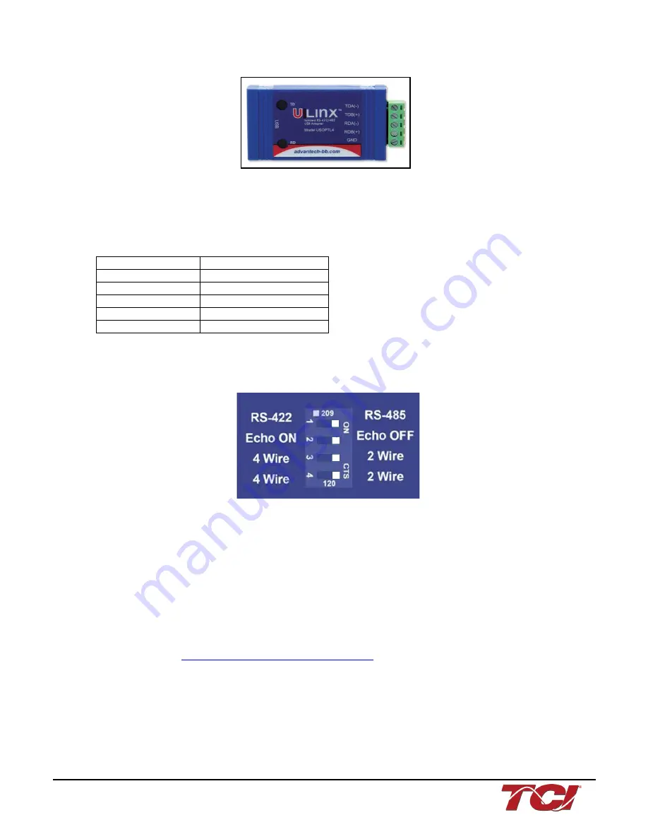
Figure 5: B&B SmartWorx, Inc Model: USPTL4 model RS-422/485 converter
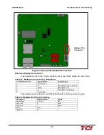
With the example converter above, the user can make proper connections from the RS485
converter to the PQconnect J5 communication header. The table below indicates the positions
where the RS485 connections lead to. Please ensure the correct dip switch settings are applied
before installing.
Table 9: USPTL4 to J5 Header Connections
USPTL4 Pin Out
J5 Header Pinout
-
No connect
TDA (-)
A (Pin 4)
GND
GND (Pin 3)
TDB(+)
B (Pin 2)
-
No connect
USPTL4 RS485 Converter Dip Switch settings
All four switches of the B&B converter from the factory should be set to the ON position and should
look like the following.
Figure 6: Dip Switch settings
Example Setup Instructions to Read Data from the PQconnect Unit:
•
Connect the cable to the “J5” communication header
•
Connect USB end to the computer
o
Determine the assigned COM port number for the RS-485 to USB converter using the
computer device manager control panel.
o
The converter used in this example typically enumerates between the range of COM5
to COM20 on a standard laptop computer running the Microsoft windows operating
system
•
Open the Simply Modbus Master software
o
Can be downloaded from the link below:
o
http://www.simplymodbus.ca/manual.htm
o
The trial version of the software is free and fully functional for this task hence no
License key is necessary
•
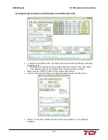
Next, configure the fields in the screen as shown below. These are again the default
settings of the PQconnect COM port.
o
Note: The “notes” section of the display data registers is filled in manually


