Section 5.0 Installation Guidelines
HGA IOM
30
The polarity of the CT is important; the “H1” marking on the CT must face the source. The
secondary windings of the CT around conductor L1 should connect to TB-1 terminals 1 & 2 and
the CT around conductor L3 should connect to TB-1 terminals 3 & 4. The secondary wire of the
CT identified as “X1” must connect to the “X1” terminal of TB-1 for both CTs. Failure to maintain
the correct polarity and phasing will cause an over-current fault. If this should happen, refer to the
troubleshooting section.
Note
: Units with black “TB-1” terminal blocks are shipped with two position shorting jumpers
installed between positions 1 & 2 and 3 & 4. This is done for safety and to prevent equipment
damage. The jumpers are installed in the center of the block and can be identified by the gray
top. After the load CTs are installed and wired, these jumpers must be removed for correct unit
operation. They can be removed with a standard flat blade screwdriver.
Note:
CT operation can be verified via the HMI touchscreen feedback waveform plot screens.
Reference the HMI VLine & ILine Waveform Plot Sub Screen for details.
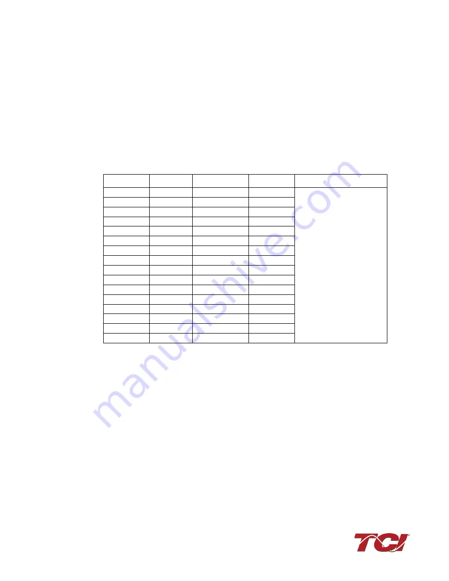
Table 14: CT Range by Model Size
Current Transformer Placement
The exact CT placement is dependent on the HGA’s configuration and size. Please refer to the
following current transformer diagrams for the installation that applies to your configuration.
The HGA is factory configured for Line Applied/Master OR Load Applied/Slave operation. A line
side unit wired with load side CT feedback or a load side unit wired for line side feedback will not
operate correctly.
Amps
Voltage
CT Min Ratio
CT Max Ratio
Notes
Up to 100
Up to 600 V
250:5
3000:5
Factory technician start up
required to use CTs outside
of the published range
150
480 V
300:5
4000:5
150
600 V
800:5
3000:5
185
600 V
600:5
5000:5
200
480 V
600:5
5000:5
220
600 V
1000:5
4000:5
250
480 V
600:5
5000:5
300
480 V
800:5
6000:5
300 (2x150)
480 V
1000:5
4000:5
300 (3x100)
480 V
800:5
5000:5
350
480 V
800:5
6000:5
370
600 V
1800:5
6000:5
400
480 V
1800:5
6000:5
500
480 V
1800:5
6000:5
600
480 V
1200:5
6000:5
700
480 V
1200:5
6000:5


