MSD Manual
4.0 Installation Guidelines
14
4.0 Installation Guidelines
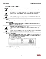
Warning
Be sure to read, understand, and follow all safety instructions provided in this manual prior to
beginning work.
Warning
Dangerous Voltage is used in the operation of the MotorShield™. Only qualified electricians
should carry out all electrical installation and maintenance work on the MotorShield™.
Warning
All wiring must be performed in accordance with the National Electrical Code (NEC) and/or
any other codes that apply to the installation site.
Wiring
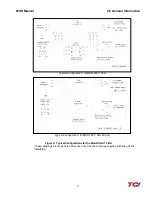
Typical wiring diagrams for filters mounted in UL Type 1 / 3R enclosures can be found in Figure
6.
Before Connecting
Always consult the drive manufacturer’s safety, installation and operation instructions prior to
connecting the MotorShield
™
to the drive.
Warning
Avoid contact with line voltage when checking for power.
Failure to follow the safety instructions set forth in this manual can result in serious injury or
death.
Warning
Exercise caution when connecting the filter to the drive. Internal filter components may carry
dangerous voltage which can cause death or serious injury upon contact.
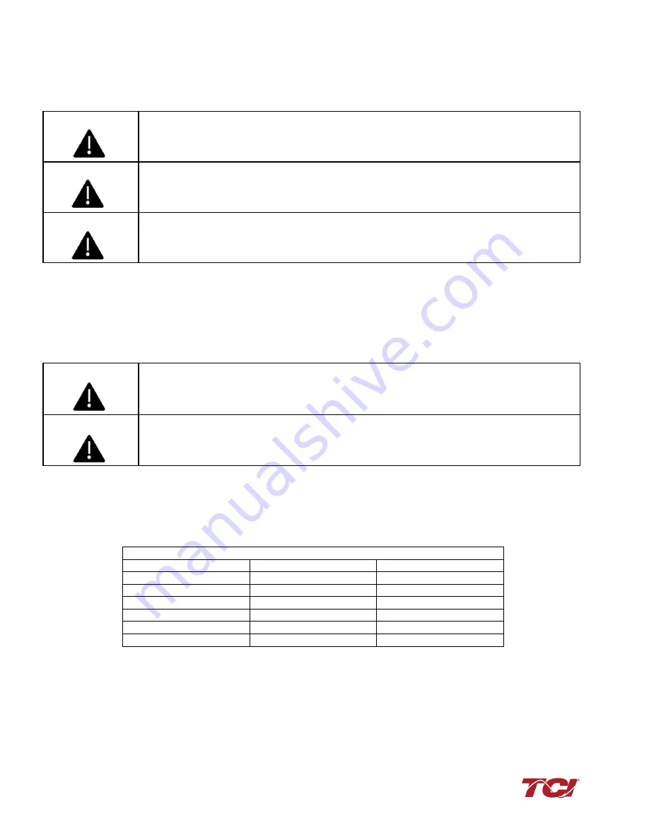
Over Temperature Switch
A set of over temperature switches is supplied to prevent damage to the filter in the rare case of
overheating due to abnormal conditions. One switch measures capacitor case temperature, the
other switch measures reactor core temperature.
Table 3: Over Temperature NC Switch
NC Switch opens on over-temperature
Current Amps
Voltage
Contact Load
6
120 AC
Non-Inductive (UL)
4
240 VAC
Non-Inductive (UL)
8
12 VDC
Resistive loads (UL)
4
24 VDC
Resistive loads (UL)
1
120 VDC
Non-Inductive (CSA)
0.7
240 VAC
Non-Inductive (CSA)
Field Wiring Connection Terminals
Compression type terminals are provided for all field wiring connections. The wire size capacity
ranges and tightening torque for the grounding and power terminals are listed in Tables 4, 5 and
6.
Summary of Contents for MotorShield MSD0009A300
Page 2: ......


