MSD Manual
2.0 General Information
3
2.0 General Information
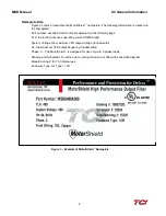
Thank you for selecting the MotorShield
™
High Performance Sine Wave Filter. TCI has produced
this filter for use in many PWM variable frequency drive (VFD) applications that require low-
distortion sine wave output power. This manual describes how to install, operate, and maintain
the MotorShield
™
filter.
Intended Audience
This manual is intended for use by all personnel responsible for the installation, operation, and
maintenance of the MotorShield
™
. Such personnel are expected to have knowledge of electrical
wiring practices, electronic components, and electrical schematic symbols.
Caution
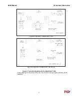
This manual provides general information describing your MotorShield™ filter. More specific
information is provided by the drawings shipped with the unit. Be sure to carefully review the
information provided by these drawings. Information provided by the drawings shipped with
the unit takes precedence over the information provided in this manual.
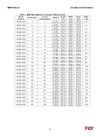
The ratings, dimensions, and weights given in this manual are approximate and should not
be used for any purpose requiring exact data. Contact the factory in situations where certified
data is required. All data is subject to change without notice.
Installation Checklist
Adhere to the following installation checklist for a successful installation. These points are
explained in detail in the subsequent sections of this manual.
Receiving Inspection
The MotorShield
™
has been thoroughly inspected, functionally tested at the factory and carefully
packaged for shipment. When you receive the unit, you should immediately inspect the shipping
•
Make sure that the installation location is appropriate for the enclosure type
selected.
•
Select a mounting area that will allow adequate cooling air and maintenance access.
•
Make sure that all wiring conforms to the requirements of the National Electrical
Code (NEC) and/or other applicable electrical codes.
•
Connect the MotorShield
™
equipment grounding lug to the system ground of the
premises wiring system. Use a properly sized grounding conductor.
•
Wire the output power terminals of the VFD, T1(U), T2(V), & T3(W) to the input
terminals of the MotorShield
™
, U, V, & W.
•
Wire the output power terminals, of the MotorShield
™
, T1, T2, & T3 to the motor.
•
Connect reactor and capacitor temperature switches to the appropriate fault
monitoring circuit.
•
Check the MotorShield
™
nameplate to ensure rated voltage is appropriate for the
power, drive and motor voltage.
•
Make sure that the VFD is set for operating modes and ranges that are compatible
with the MotorShield
™
.
•
Confirm the drive operation mode is set to Volts per Hertz mode prior to operation.
Consult the drive manufacturer for compatibility settings for use with sine wave
filters.
•
Check the installation thoroughly before operating the equipment.
Summary of Contents for MotorShield MSD0009A300
Page 2: ......


