TCL-THOMSON Electronics R&D Center (Shen’Zhen Lab)
Chassis Name
NX56-LA
Serial No.
Issued on
2008-05-19
Page
Page 13 of 15
Updated on
2010-01-27
Version
2.2
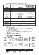
On producing, these geometry offset datum can use to easy the NTSC geometry
adjustment. When finished the PAL geometry adjustment, trigger the “AUTO OFFSET”
from “0” to “1”, then the
geometry adjustment of NTSC signal will finish automated. If now
the geometry of NTSC signal is look good, it not needed to adjust the geometry of NTSC
signal any more.
3.
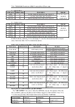
Enter P-Mode, press key “6” to select page “6”. Set the corresponding item to require
value. See below table 3.6.3 for detailed description.
Table 3.6.3: Producing parameter setup and option page “6”
OSD menu
Default
Value
Description Remark
AGCT
32
AGC take over point
See section “3.2
RF AGC alignment” for detailed.
OIF
32
IF demodulator offset
Don’t adjust, use default
IF
45.7
IF frequency
Select the IF frequency
AGCS
1
AGC speed
Don’t adjust, use default
AGNE
3
Audio gain
Don’t adjust, use default
WATCHDOG
8
Don’t adjust, use default
BLUE BLACK
OPT
0
No signal background
color set
0=BLUE
1=BLACK
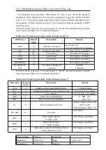
4.
Enter P-Mode, press key “7” to select page “7”. Set the corresponding item to require
value. See below table 3.6.4 for detailed description.
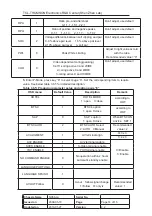
Table 3.6.4: Producing parameter setup and option page “7”
OSD menu
Default
Value
Description Remark
EVG
0
Enable vertical guard(RGB blanking)
1= RGB blanking
DFL
0
Disable flash protection from defletion timer
Don’t adjust, use default
XDT 0
X-ray
detection
Don’t adjust, use default
AKB 1
Black
current
stabilization
NBL
1
Black current loop application
0 AKB ON
1 AKB OFF
CL
10
Set the cathode drive level
Adjust to right value accord
with the tube.
Recommended value= “12”
CC-LINE 21
CC’s
line
Don’t adjust
BKS 1
Black Stretch Switch
0 =OFF,1 =ON
Don’t adjust, use default
BSD 0
Black Stretch depth
0
ˉ
15IRE,1-30IRE
Don’t adjust, use default
AAS 0
Black area to switch off the black stretch
0-12%1-20%,2-6%,3-8%
Don’t adjust, use default

