TCL-THOMSON Electronics R&D Center (Shen’Zhen Lab)
Chassis Name
NX56-LA
Serial No.
Issued on
2008-05-19
Page
Page 8 of 15
Updated on
2010-01-27
Version
2.2
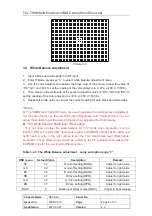
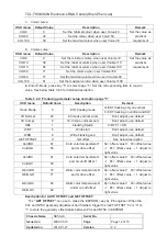
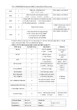
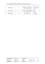
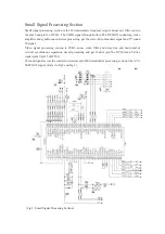
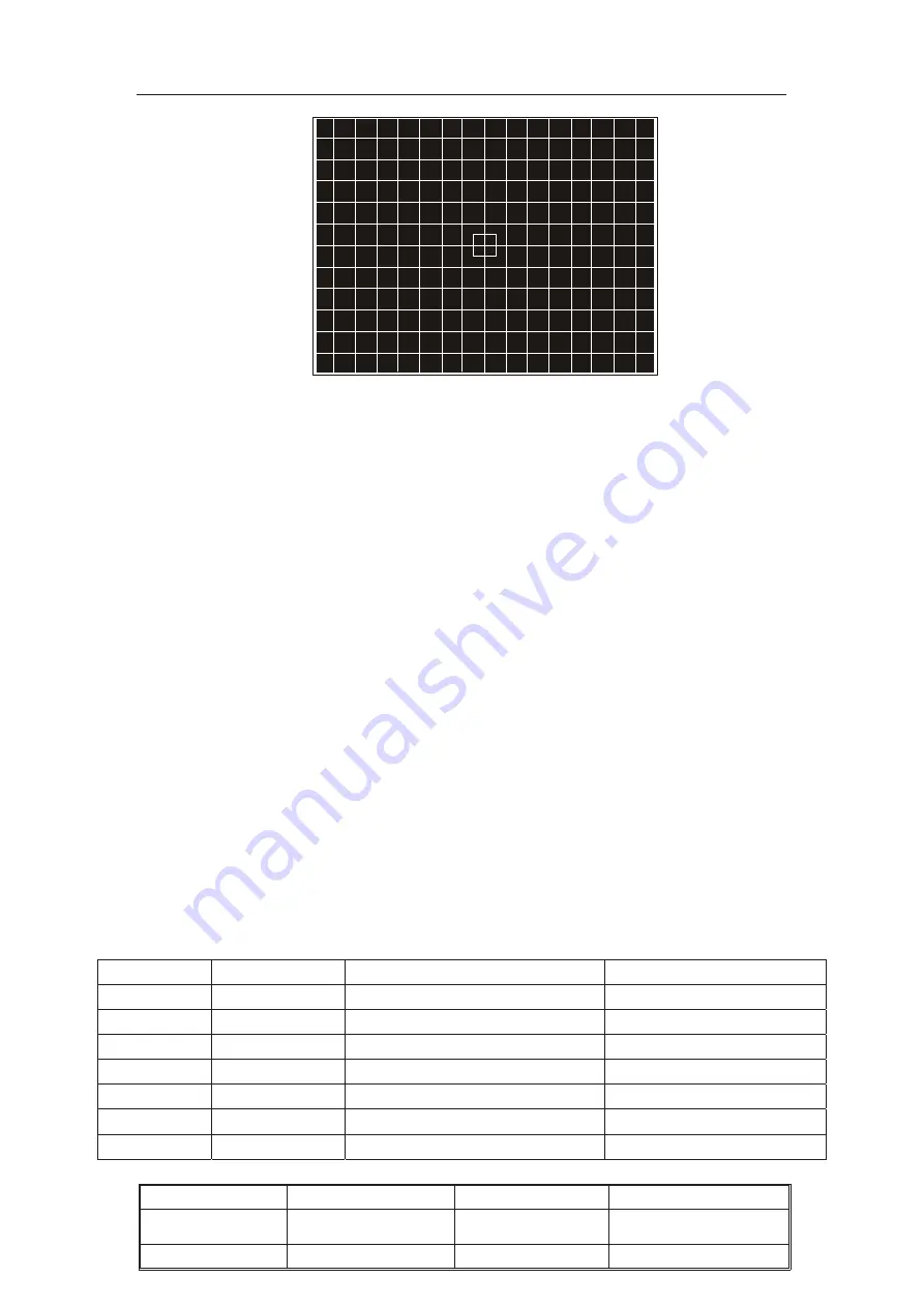
Picture 3.3
3.4 White Balance Adjustment
1. Input a black and white pattern to RF input.
2. Enter P-Mode, press key “3 ” to select white balance adjustment menu.
3. Use the color analyzer to measure the black side of the screen. Adjust the value of
“RC”,”GC” and “BC” to set the reading of the color analyzer to x=274, y=280. (11500 K).
4. Then measure the white side of the screen. Adjust the value of “RD”, “GD” and “BD” to
set the reading of the color analyzer to x=274, y=280. (11500 K).
5. Repeat step 3&4 until you can get the correct reading for both black and white sides.
*Notes:
A.
The “SUBB” and “SubCON” items are used to assistant the white balance adjustment.
It is the same function as the user OSD menu “Brightness” and “Contrast” items. You can
adjust these items to get the expect intensity when adjusting the white balance.
B.
YUV white balance black level offset setup:
It is not need to adjust the white balance for YUV mode when production, but the
BLOR-Y, BLOG-Y and BLOB-Y items which locate in EEPROM address 0x0A, 0x0B and
0x0C need to write in the right values to set the YUV mode black level offset before
production. These offset values should be written by the PE engineer when making the
EEPROM copy for the new lot with difference tube.
Table 3.4.1: The White Balance adjustment setup and option page “3”
OSD menu
Default Value
Description
Remark
RC
32
R cut-off setting(BLOR)
Adjust to right value
GC
32
G cut-off setting(BLOG)
Adjust to right value
BC
32
B cut-off setting(BLOB)
Adjust to right value
RD
37
R drive setting(WPR)
Adjust to right value
GD
32
G drive setting(WPG)
Adjust to right value
BD
37
B drive setting(WPB)
Adjust to right value
BLOC
8
Black level offset course(BLOC)
Adjust to right valuege


