background image

11.

Do not use this television set near water ... for example, near a bathtub, washbowl, kitchen sink, or laundry tub, in a

wet basement, or near a swimming pool, etc.

Never expose the set to rain or water. If the set has been exposed to rain or water, unplug the set from the wall

outlet and refer servicing to qualified service personnel.

12. Choose a place where light (artificial or sunlight) does not shine directly on the screen.

13. Avoid dusty places, since piling up of dust inside TV chassis may cause failure of the set when high humidity persists.

14. The set has slots, or openings in the cabinet for ventilation purposes, to provide reliable operation of the receiver, to

protect it from overheating. These openings must not be blocked or covered.

Never cover the slots or openings with cloth or other material.
Never block the bottom ventilation slots of the set by placing it on a bed, sofa, rug, etc.
Never place the set near or over a radiator or heat register.
Never place the set in

enclosure, unless proper ventilation is provided.

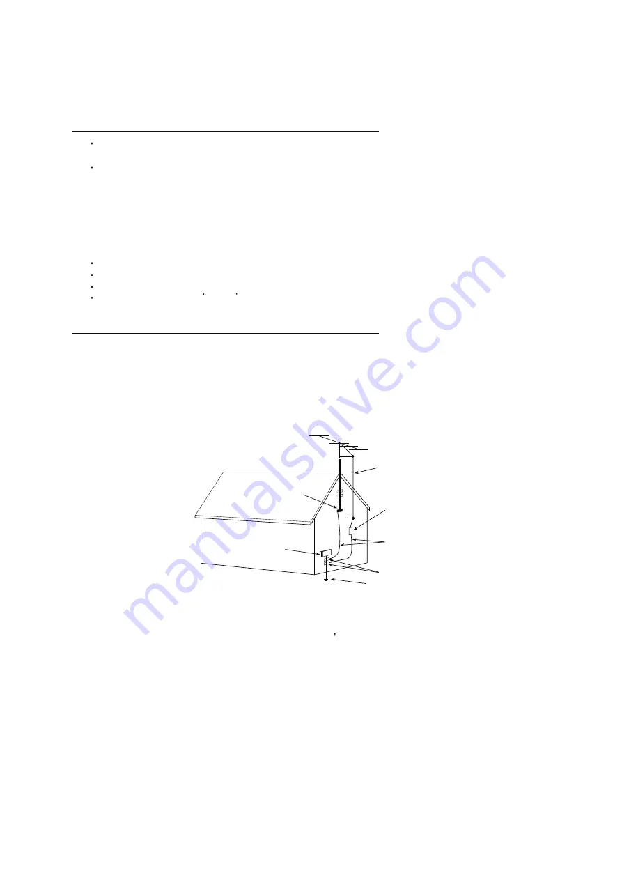
15.1. If an outside antenna is connected to the television set, be sure the antenna system is grounded so as to provide some

protection against voltage surges and built up static charges, Section 810 of the National Electrical Code, NFPA No.
70-1975, provides information with respect to proper grounding of the mast and supporting structure, grounding of the
lead-in wire to an antenna discharge unit, size of grounding conductors, location of antenna discharge unit, connection
to grounding electrode, and requirements for the grounding electrode.

15.2. Note to CATV system installer : (Only for the television set with CATV reception)

This reminder is provided to call the CATV system

attention to Article 820-40 of the NEC that provides

guidelines for proper grounding and, in particular, specifies that the cable ground shall be connected to the grounding
system of the building, as close to the point of cable entry as practical.

16.

An outside antenna system should not be located in the vicinity of overhead power lines or other electric lights or power
circuits, or where it can fall into such power lines or circuits. When installing an outside antenna system, extreme care
should be taken to keep from touching such power lines or circuits as contact with them might be fatal.

17.

For added protection for this television set during a lightning storm, or when it is left unattended and unused for long
periods of time, unplug it from the wall outlet and disconnect the antenna. This will prevent damage due to lightning
and power-line surges.

ANTENNA

LEAD- IN WIRE

ANTENNA DISCHARGE

UNIT (NEC SECTION

810-20)

GROUNDING

CONDUCTORS

(NEC SECTION810-21)

GROUND CLAMPS

POWER SERVICE GROUNDING

ELECTRODE SYSTEM

(NEC ART 250. PART H)

ELECTRIC SERVICE

EQUIPMENT

GROUND CLAMP

NEC-NATIONAL ELECTRICAL CODE

EXAMPLE OF ANTENNA GROUNDING AS PER
NATIONAL ELECTRICAL CODE

EXAMPLE OF ANTENNA GROUNDING AS PER NATIONAL ELECTRICAL CODE INSTRUCTIONS

a built-in

installer s

4

SCHNEIDER ELECTRONICS GMBH-GERMANY

PROTECTION AND LOCATION OF YOUR SET

PROTECTION AND LOCATION OF YOUR SET

4

Summary of Contents for 32D1281

Page 1: ...fication 3 Alignment Procedure 4 Scheme Diagram 5 Troubleshooting 6 Explode drawing This manual is t he latest at the time of printing and does not include the modification which may be made after the...

Page 2: ...lectric shock to the person The exclamation point within an equilateral triangle is intended to alert the user to the presence of important operating and maintenance servicing instructions in the lite...

Page 3: ...impact of any kind Be particularly careful not to damage the picture tube surface 9 Unplug this television set from the wall outlet before cleaning Do not use liquid cleaners or aerosol cleaners Use...

Page 4: ...ng conductors location of antenna discharge unit connection to grounding electrode and requirements for the grounding electrode 15 2 Note to CATV system installer Only for the television set with CATV...

Page 5: ...durein youroperatinginstructions do not attempt any further adjustment Unplug the set and call your dealer or service technician 22 Whenever the television set is damaged or fails or a distinct change...

Page 6: ...000hrs EPG Yes at DTV Color 16 7M 8 bit Closed Caption Yes Refresh Rate 60Hz Parental Control Yes Sleep Timer Yes System Update Yes HDMI 2 Hotel Mode USB 2 Input Method Virtual keyboard AV in 1 MHL YP...

Page 7: ...3 Carton Dimensions LxWxH mm 800 128 520 W2 mm 182 Container Loading 20 feet pcs 504 H2 mm 478 3 Container Loading 40 feet pcs 1008 Net Weight With Stand Kg 3 81 Container Loading 40 feet High pcs 124...

Page 8: ...7 SCBC R D NT72563 Factory Menu Spec V1 0 2017 10 17 Drafted by Checked by Approved By Kim yuan N 21...

Page 9: ...TENTS 1 INTRODUCTION 1 2 OPEN THE FACTORY MENU METHOD 1 3 WHITE BALANCE 2 4 OTHER SUBMENU 3 5 NVM RESET SUBMENU 4 6 PRESET FACTORY CHANNEL SUBMENU 4 7 POWER ON MODE SUBMENU 4 8 USB CLONE UPDATE SUBMEN...

Page 10: ...tiFactory mode data reset It will be done before shop initial if needroduct line HOTKEY will be di White Balance WhiteBalance Adjustment Other Set some TV setup NVM reset Do Clear NVM values Preset Fa...

Page 11: ...ssing key B Offset 0 255 Set B Offset by pressing key White Balance Init Do Press key to initialize RGB Gain Offset values Picture Related Press key to activate submenu Item Sub item Value Note Pictur...

Page 12: ...e info Panel info RCU info Region info PSU info Running Time info Grey Ctl Grey Ctl Select Grey ctrl ON or OFF by pressing key to control picture menu Grey or not Update CI Credential Update CI Creden...

Page 13: ...ect starting sequence by pressing key ON Force TV to start STB Force TV to standby LAST Force TV to standby or to start depending on latest operation 8 USB Clone Update submenu Item Sub item Value Not...

Page 14: ...5 Index V1 0 of 5 pages Name HDCP2 0 Upgrade Press ok key to upgrade HDCP2 0 key HDCP Upgrade Press ok key to upgrade HDCP key WideVine Upgrade Press ok key to upgrade WideVine Device id Upgrade Pres...

Page 15: ...JP1 JP2 a EB2 a a RB148 a EB1 1 1 HS 2 2 HSB3 12V NC CYB4 NC CYB5 L RB113 RB103 SGND BRO RB141 RB142 CB111 L GND 1 COMP 2 NC 3 CS 4 VCC 5 GATE 6 UB101 RB104 D G S QB101 a 1 1 HS 2 2 HSB1 1 1 HS 2 2 HS...

Page 16: ...PIRD1002 CORD10 PIRD1101 PIRD1102 CORD11 PIRD1201 PIRD1202 CORD12 PIRD1301 PIRD1302 CORD13 PIRD1401 PIRD1402 CORD14 PIRD1501 PIRD1502 CORD15 PIRD1601 PIRD1602 CORD16 PIRD1701 PIRD1702 CORD17 PIRD1801...

Page 17: ..._M A_SC L W 6 G PD _2 PTSI N 1_VALI D STSI N 1_VALI D I 2C _M B_S V6 G PD _3 PTSI N 1_STAR T STSI N 1_STAR T I 2C _M B_S U 6 G PD _4 PTSI N 1_D 0 STSI N 1_D ATA I 2C _M C _SD A P T6 G PD _5 PTSI N 1_D...

Page 18: ...COR12 PIR1301 PIR1302 COR13 PIR1401 PIR1402 COR14 PIR1501 PIR1502 COR15 PIR1601 PIR1602 COR16 PIR1701 PIR1702 COR17 PIR1901 PIR1902 COR19 PIR2001 PIR2002 COR20 PIR2101 PIR2102 COR21 PIR2201 PIR2202 C...

Page 19: ...43602 COR436 PIR43701 PIR43702 COR437 PIR43801 PIR43802 COR438 PIR43901 PIR43902 COR439 PIR44001 PIR44002 COR440 PIR44101 PIR44102 COR441 PIR44201 PIR44202 COR442 PIR44401 PIR44402 COR444 PIR44501 PIR...

Page 20: ...QH1 PIQH20B PIQH20C PIQH20E COQH2 PIQH30B PIQH30C PIQH30E COQH3 PIQH40B PIQH40C PIQH40E COQH4 PIQH50B PIQH50C PIQH50E COQH5 PIQH60B PIQH60C PIQH60E COQH6 PIQH70B PIQH70C PIQH70E COQH7 PIR11201 PIR1120...

Page 21: ...PICNF209 PICNF2010 PICNF2011 PICNF2012 PICNF2013 PICNF2014 PICNF2015 PICNF2016 PICNF2017 PICNF2018 PICNF2019 PICNF2020 PICNF2021 PICNF2022 PICNF2023 PICNF2024 PICNF2025 PICNF2026 PICNF2027 PICNF2028 P...

Page 22: ...03 PICN1104 PICN1105 COCN11 PIDF30A PIDF30K CODF3 PIDI20A PIDI20K CODI2 PIDI30A PIDI30K CODI3 PIDI40A PIDI40K CODI4 PIDI60A PIDI60K CODI6 PIR5401 PIR5402 COR54 PIR7301 PIR7302 COR73 PIRF1601 PIRF1602...

Page 23: ...90K CODU19 PIED301 PIED302 COED3 PILW101 PILW102 PILW103 PILW104 COLW1 PILW201 PILW202 PILW203 PILW204 COLW2 PIR2901 PIR2902 COR29 PIRE101 PIRE102 CORE1 PIRE901 PIRE902 CORE9 PIRE1001 PIRE1002 CORE10...

Page 24: ...101 PILT1102 COLT11 PILT1201 PILT1202 COLT12 PILT1301 PILT1302 COLT13 PILT1501 PILT1502 COLT15 PILTT101 PILTT102 COLTT1 PIRFT101 PIRFT102 PIRFT103 PIRFT104 PIRFT105 CORFT1 PIRFT201 PIRFT202 PIRFT203 P...

Page 25: ...A1602 CORA16 PIRA1701 PIRA1702 CORA17 PIRA1801 PIRA1802 CORA18 PIRA1901 PIRA1902 CORA19 PIRA2001 PIRA2002 CORA20 PIRA2101 PIRA2102 CORA21 PIRA2201 PIRA2202 CORA22 PIRA2301 PIRA2302 CORA23 PIRA2401 PIR...

Page 26: ...al Signal output from processor and input for panel O C Open Cell panel with source board BL Back Light light source for panel module LB LED Light Emitting Diode Bar light source for BL module VBL Vol...

Page 27: ...1 No power No power LED RC or Key can not turn on TV Power LED no light no change...

Page 28: ...2 No Display Black Panel Back light is OK sound is OK but no picture...

Page 29: ...3 No back light Power LED logic OK sound OK but no picture Different from No Display...

Page 30: ...4 No sound One or all signal source without sound...

Page 31: ...5 Signal source no function One or several source no function...

Page 32: ...6 Abnormal Display OSD NG or picture NG...

Reviews: