background image

1

1

2

2

3

3

4

4

5

5

6

6

D

D

C

C

B

B

A

A

VDD33_USB

2V5_M_SIFADC

2V5_M_TVADC

GND

VDD09_STBC

VDD33_STBC

VDD33

VDD33_AUDAC

2V5_M_SIFADC

VDD_EMMC

2V5_M_TVADC

GND

VDD33_USB

VDD33_AUDAC

2V5_M_TVADC

GND

VDD33_STBC

VDD_EMMC

GND

VDD33

2V5_M_SIFADC

GND

VDD09_STBC

GND

GND

GND

C37

C36

C38 C39 C40 C41 C42

C44

C43

C46

C45

C53

GND

C29

C28

GND

C24

C23

C25 C26 C27

GND

C31

C30

GND

C33

C32

C34 C35

GND

C21

C20

C22

GND

C17

C16

GND

C19

C18

L7

L8

L2

L4

L6

C14 C15

R19

R6

R7
R11
R13
R15

R20 R21 R22 R23

R8

R14
R16
R17

R12

R24

R26 R27 R28

R25

BS0_I C

3V3_M

3V3_STB

BS4_IC

BS3_IC

BS9_IC

BS8_IC

3V3_STB

BS12_IC

LED_OUT_IC

BS19_IC
BS20_IC

BS15_IC

2V5_M

CORE_0.9V

1.5V_DDR

2V5_M

CORE_0.9V

3V3_STB

VDD33_STBC

1.8_EMMC

VDD_EMMC

3V3_M

VDD33

VDD33_AUDAC

1.5V_DDR

C71

2V5_M

CORE_0.9V

C56

2V5_M

3V3_M

VDD33_USB

RH39

CH33

GND

5V_M

R30

C72

GND

Q1

R2

PCB

R32

L3

VDD33_NET

VDD33_NET

C52

VDD33_AUADC

K17

VDD09_DDR

E5

VDD33_HDMI

U15

GND

L17

VDD25_TVADC1

N19

VDD25_TVDAC

M15

V

D

D

3

3

_

S

T

B

C

T

1

7

VDD25_MPLL

N16

V

D

D

3

3

_

E

T

H

E

R

N

E

T

T

1

6

GND

U1

GND

R14

VDD33_AUDAC

J17

VDD33_I O

R15

VDD25_SI FADC0

J19

V

D

D

3

3

_

X

T

A

L

R

1

7

VDD25_TVADC0

M18

GND

K14

VDD_CORE

D5

VDD_CORE

C5

VDD_CORE

C4

VDD_CORE

B5

VDD_CORE

B4

VDD_CORE

A5

VDD15_MMU

P11

VDD15A_MMU

F1

VDD33_USB2

P14

GND

J14

GND

N17

GND

A1

GND

J8

GND

J9

GND

J10

GND

K6

GND

M10

GND

N2

GND

N7

GND

N8

GND

N9

GND

N10

VDD15_MMU

M12

GND

P7

GND

P9

GND

R1

GND

R7

GND

V2

GND

AC1

GND

AC23

VDD15_MMU

G3

VDD15_MMU

G4

GND

K15

GND

L2

GND

AA3

GND

AA4

VDD_CORE

A4

GND

L15

VDD25_LVDS

K13

VDD25_LVDS

J13

GND

P10

VDD25_SI FADC1

H19

GND

M9

V

D

D

1

0

_

S

T

B

C

Y

2

0

GND

Y3

VDD33_USB0

P15

VDD25_APLL

M16

GND

J20

VDD25_BI AS

N18

VDD15A_MMU

F2

VDD15A_MMU

N12

VDD15_LDO

N11

VDD15_KGD

G1

VDD15_KGD

G2

GND

J15

GND

L16

GND

M1

GND

M5

GND

M17

GND

J3

VDD33_HDMI

T15

GND

L6

GND

P2

GND

T2

GND

V4

GND

K3

GND

N4

GND

R11

GND

U5

GND

Y5

GND

G20

GND

G19

GND

AA12

GND

G18

GND

H18

GND

H20

GND

N21

V

D

D

_

E

M

M

C

A

C

2

2

GND

K16

VDD15_CLK

F3

VDD25_DLL

L13

U27I

VDD33_NET

C7

GND

Summary of Contents for 43D1240

Page 1: ...ification 3 Alignment Procedure 4 Scheme Diagram 5 Troubleshooting 6 Explode drawing This manual is t he latest at the time of printing and does not include the modification which may be made after the printing by the constant improvement of product ...

Page 2: ...electric shock to the person The exclamation point within an equilateral triangle is intended to alert the user to the presence of important operating and maintenance servicing instructions in the literature accompanying the appliance CAUTION Use of controls adjustments or procedures other than those specified herein may result in hazardous radiation exposure CA U T ION RISK RISK OF ELECTRI ELECTR...

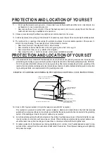
Page 3: ...o impact of any kind Be particularly careful not to damage the picture tube surface 9 Unplug this television set from the wall outlet before cleaning Do not use liquid cleaners or aerosol cleaners Use a damp cloth for cleaning 10 1 Do not place this television set on an unstable cart stand or table The television set may fall causing serious injury to a child or an adult and serious damage to the ...

Page 4: ...ing conductors location of antenna discharge unit connection to grounding electrode and requirements for the grounding electrode 15 2 Note to CATV system installer Only for the television set with CATV reception This reminder is provided to call the CATV system attention to Article 820 40 of the NEC that provides guidelines for proper grounding and in particular specifies that the cable ground sha...

Page 5: ...edurein youroperatinginstructions do not attempt any further adjustment Unplug the set and call your dealer or service technician 22 Whenever the television set is damaged or fails or a distinct change in performance indicates a need for service unplug the set and have it checked by a professional service technician 23 It is normal for some TV sets to make occasional snapping or popping sounds par...

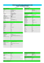
Page 6: ...Lightsensor AUDIO out 1 GINGA Yes VGA in No CEC Yes VGA audio in No ARC Yes RJ45 1 Time shift Yes SPDIF out Coaxial PVR Yes Earphone out 0 RF Input 2 DCC Dynamic Contrast Control Yes Backlight Adjustable Yes 0 100 Color Temperature Cool Normal Warm custom Picture Mode Standard Dynamic Natural Movie Stadium Persanal Picture Size 16 9 format 4 3 format Cinerama 16 9 Zoom 16 9 zoom up 14 9 zoom Pictu...

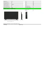
Page 7: ...t pcs 246 H2 mm 611 2 Container Loading 40 feet pcs 510 Net Weight With Stand Kg 7 1 Container Loading 40 feet High pcs 676 Net Weight Without Stand Kg 7 0 VESA Mounting Dimensions LxH mm 200 100 Gross Weight With Packaging Kg 9 8 RF 2 4G and Air mouse No IR Remote Yes Voice Control No Design and specifications are subject to change without notice Drafted by Approved by Remote Performance and ID P...

Page 8: ...7 ཊჂփ ᢰ᧗㛑ᴹ䲀 ޜ ਨ SCBC R D NT72563 Factory Menu Spec V1 0 2017 10 17 Drafted by Checked by Approved By Kim yuan ᮷Ԧ㕆ਧ N ޡ 21 亥 ...

Page 9: ...NTENTS 1 INTRODUCTION 1 2 OPEN THE FACTORY MENU METHOD 1 3 WHITE BALANCE 2 4 OTHER SUBMENU 3 5 NVM RESET SUBMENU 4 6 PRESET FACTORY CHANNEL SUBMENU 4 7 POWER ON MODE SUBMENU 4 8 USB CLONE UPDATE SUBMENU 4 ...

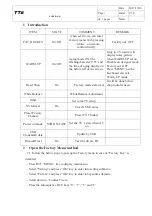
Page 10: ...itiFactory mode data reset It will be done before shop initial if needroduct line HOTKEY will be di White Balance WhiteBalance Adjustment Other Set some TV setup NVM reset Do Clear NVM values Preset Factory Channel Preset TV Channel Power on mode STB ON LAST Set the TV s state when AC on USB Clone Udate Update by USB DiveceID test Do Test the divece ID 2 Open the Factory Menu method 2 1 Follow the...

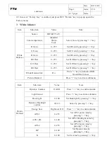
Page 11: ...essing key B Offset 0 255 Set B Offset by pressing key White Balance Init Do Press key to initialize RGB Gain Offset values Picture Related Press key to activate submenu Item Sub item Value Note Picture Related Dynamic Contrast On Off Press key to enable disable Light Sensor Press key to activate submenu Back light 0 100 Set Backlight by pressing key Dynamic Backlight control 0 1 2 3 Select by pre...

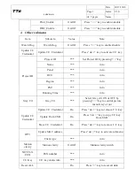
Page 12: ...me info Panel info RCU info Region info PSU info Running Time info Grey Ctl Grey Ctl Select Grey ctrl ON or OFF by pressing key to control picture menu Grey or not Update CI Credential Update CI Credential Do Press ok key to remove CI key Update From USB Do Press ok key to copy CI key from USB Erase CI Credential Do Press ok key to remove CI key IPTV Update MAC address Press ok key to activate sub...

Page 13: ...lect starting sequence by pressing key ON Force TV to start STB Force TV to standby LAST Force TV to standby or to start depending on latest operation 8 USB Clone Update submenu Item Sub item Value Note USB Clone Update Main Upgrade Press ok key to update main software FRC Upgrade Press ok key to update FRC software FRC Backup Press ok key to copy FRC software to USB USB TO TV ALL UserData CH list...

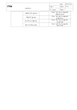
Page 14: ...e 5 Index V1 0 of 5 pages Name HDCP2 0 Upgrade Press ok key to upgrade HDCP2 0 key HDCP Upgrade Press ok key to upgrade HDCP key WideVine Upgrade Press ok key to upgrade WideVine Device id Upgrade Press ok key to upgrade Device ID ...

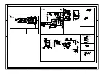
Page 15: ... JP1 JP2 a EB2 a a RB148 a EB1 1 1 HS 2 2 HSB3 12V NC CYB4 NC CYB5 L RB113 RB103 SGND BRO RB141 RB142 CB111 L GND 1 COMP 2 NC 3 CS 4 VCC 5 GATE 6 UB101 RB104 D G S QB101 a 1 1 HS 2 2 HSB1 1 1 HS 2 2 HSB2 D_QB101 D_QB101 a a a a a a GND GND LED_OVP LEDa LED_GATE a EB801 a EB802 BB801 RB811 RB810 RB807 RB808 DB809 RB809 D_QB801 RB818 RB805 LED_CS CB815 LEDa GND LB801 VBL CB804 GND LED1 LED2 LED3 LED...

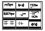
Page 16: ...1001 PIRD1002 CORD10 PIRD1101 PIRD1102 CORD11 PIRD1201 PIRD1202 CORD12 PIRD1301 PIRD1302 CORD13 PIRD1401 PIRD1402 CORD14 PIRD1501 PIRD1502 CORD15 PIRD1601 PIRD1602 CORD16 PIRD1701 PIRD1702 CORD17 PIRD1801 PIRD1802 CORD18 PIRD1901 PIRD1902 CORD19 PIRD2001 PIRD2002 CORD20 PIRD2101 PIRD2102 CORD21 PIRD2401 PIRD2402 CORD24 PIRD2501 PIRD2502 CORD25 PIRD2601 PIRD2602 CORD26 PIRD2701 PIRD2702 CORD27 PIRG...

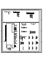
Page 17: ... _M A_SC L W 6 G PD _2 PTSI N 1_VALI D STSI N 1_VALI D I 2C _M B_S V6 G PD _3 PTSI N 1_STAR T STSI N 1_STAR T I 2C _M B_S U 6 G PD _4 PTSI N 1_D 0 STSI N 1_D ATA I 2C _M C _SD A P T6 G PD _5 PTSI N 1_D 1 I 2C _M C _SC L PTSI N 2_D 1 U 7 G PD _6 PTSI N 1_D 2 I 2S_I N _D ATA PTSI N 2_D 2 AA9 G PD _7 PTSI N 1_D 3 I 2S_I N _W S PTSI N 2_D 3 U 8 G PD _8 PTSI N 1_D 4 I 2S_I N _M C LK D EM O D _Q LED P T...

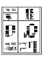
Page 18: ...02 COR12 PIR1301 PIR1302 COR13 PIR1401 PIR1402 COR14 PIR1501 PIR1502 COR15 PIR1601 PIR1602 COR16 PIR1701 PIR1702 COR17 PIR1901 PIR1902 COR19 PIR2001 PIR2002 COR20 PIR2101 PIR2102 COR21 PIR2201 PIR2202 COR22 PIR2301 PIR2302 COR23 PIR2401 PIR2402 COR24 PIR2501 PIR2502 COR25 PIR2601 PIR2602 COR26 PIR2701 PIR2702 COR27 PIR2801 PIR2802 COR28 PIR3001 PIR3002 COR30 PIR3201 PIR3202 PIR3203 COR32 PIRH3901 ...

Page 19: ...R43602 COR436 PIR43701 PIR43702 COR437 PIR43801 PIR43802 COR438 PIR43901 PIR43902 COR439 PIR44001 PIR44002 COR440 PIR44101 PIR44102 COR441 PIR44201 PIR44202 COR442 PIR44401 PIR44402 COR444 PIR44501 PIR44502 COR445 PIR44601 PIR44602 COR446 PIR44701 PIR44702 COR447 PIR44801 PIR44802 COR448 PIRD2201 PIRD2202 CORD22 PIRD2301 PIRD2302 CORD23 PIU10A1 PIU10A2 PIU10A3 PIU10A4 PIU10A5 PIU10A6 PIU10A8 PIU10...

Page 20: ...OQH1 PIQH20B PIQH20C PIQH20E COQH2 PIQH30B PIQH30C PIQH30E COQH3 PIQH40B PIQH40C PIQH40E COQH4 PIQH50B PIQH50C PIQH50E COQH5 PIQH60B PIQH60C PIQH60E COQH6 PIQH70B PIQH70C PIQH70E COQH7 PIR11201 PIR11202 COR112 PIR11301 PIR11302 COR113 PIRH101 PIRH102 CORH1 PIRH201 PIRH202 CORH2 PIRH301 PIRH302 CORH3 PIRH401 PIRH402 CORH4 PIRH501 PIRH502 CORH5 PIRH601 PIRH602 CORH6 PIRH701 PIRH702 CORH7 PIRH801 PIR...

Page 21: ... PICNF209 PICNF2010 PICNF2011 PICNF2012 PICNF2013 PICNF2014 PICNF2015 PICNF2016 PICNF2017 PICNF2018 PICNF2019 PICNF2020 PICNF2021 PICNF2022 PICNF2023 PICNF2024 PICNF2025 PICNF2026 PICNF2027 PICNF2028 PICNF2029 PICNF2030 PICNF2031 PICNF2032 COCNF2 PICNK101 PICNK102 PICNK103 PICNK104 PICNK105 COCNK1 PICNK1101 PICNK1102 COCNK11 PIDK10A PIDK10K CODK1 PIR101 PIR102 COR1 PIRK101 PIRK102 CORK1 PIRK201 PI...

Page 22: ...103 PICN1104 PICN1105 COCN11 PIDF30A PIDF30K CODF3 PIDI20A PIDI20K CODI2 PIDI30A PIDI30K CODI3 PIDI40A PIDI40K CODI4 PIDI60A PIDI60K CODI6 PIR5401 PIR5402 COR54 PIR7301 PIR7302 COR73 PIRF1601 PIRF1602 CORF16 PIRI501 PIRI502 CORI5 PIRI601 PIRI602 CORI6 PIRI801 PIRI802 CORI8 PIRI1001 PIRI1002 CORI10 PIRI1201 PIRI1202 CORI12 PIRI1601 PIRI1602 CORI16 PIRI2001 PIRI2002 CORI20 PIRF1601 PICI401 NLAV0YPbP...

Page 23: ...190K CODU19 PIED301 PIED302 COED3 PILW101 PILW102 PILW103 PILW104 COLW1 PILW201 PILW202 PILW203 PILW204 COLW2 PIR2901 PIR2902 COR29 PIRE101 PIRE102 CORE1 PIRE901 PIRE902 CORE9 PIRE1001 PIRE1002 CORE10 PIRE1201 PIRE1202 CORE12 PIRE5001 PIRE5002 CORE50 PIRE5101 PIRE5102CORE51 PIRE5201 PIRE5202 CORE52 PIRE5301 PIRE5302 CORE53 PIRF201 PIRF202 CORF2 PIRF301 PIRF302 CORF3 PIRF401 PIRF402 CORF4 PIRF501 P...

Page 24: ...1101 PILT1102 COLT11 PILT1201 PILT1202 COLT12 PILT1301 PILT1302 COLT13 PILT1501 PILT1502 COLT15 PILTT101 PILTT102 COLTT1 PIRFT101 PIRFT102 PIRFT103 PIRFT104 PIRFT105 CORFT1 PIRFT201 PIRFT202 PIRFT203 PIRFT204 PIRFT205 CORFT2 PIRT101 PIRT102 CORT1 PIRT201 PIRT202 CORT2 PIRT301 PIRT302 CORT3 PIRT401 PIRT402 CORT4 PIRT501 PIRT502 CORT5 PIRT601 PIRT602 CORT6 PIRT701 PIRT702 CORT7 PIRT801 PIRT802 CORT8...

Page 25: ...IRA1602 CORA16 PIRA1701 PIRA1702 CORA17 PIRA1801 PIRA1802 CORA18 PIRA1901 PIRA1902 CORA19 PIRA2001 PIRA2002 CORA20 PIRA2101 PIRA2102 CORA21 PIRA2201 PIRA2202 CORA22 PIRA2301 PIRA2302 CORA23 PIRA2401 PIRA2402 CORA24 PIRA2501 PIRA2502 CORA25 PIRA3501 PIRA3502 CORA35 PIRA5101 PIRA5102 CORA51 PIRA5201 PIRA5202 CORA52 PIRA5401 PIRA5402 CORA54 PIRA550JP01K PIRA550JP02K CORA55 PIRA560JP01K PIRA560JP02K C...

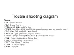
Page 26: ...ial Signal output from processor and input for panel O C Open Cell panel with source board BL Back Light light source for panel module LB LED Light Emitting Diode Bar light source for BL module VBL Voltage for Back Light before Boost VLED Voltage for LED after Boost OVP Over Voltage Protection OSD On Screen Display AMP Amplifier ...

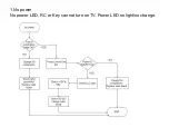
Page 27: ...1 No power No power LED RC or Key can not turn on TV Power LED no light no change ...

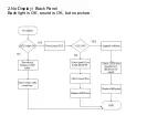
Page 28: ...2 No Display Black Panel Back light is OK sound is OK but no picture ...

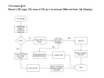
Page 29: ...3 No back light Power LED logic OK sound OK but no picture Different from No Display ...

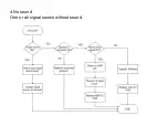
Page 30: ...4 No sound One or all signal source without sound ...

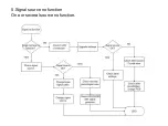
Page 31: ...5 Signal source no function One or several source no function ...

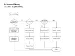
Page 32: ...6 Abnormal Display OSD NG or picture NG ...

Page 33: ......

Reviews: