Factory Alignment Specification of normal SIACP
Page 5 of 12
INFO
ª
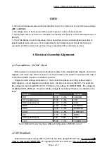
All tests and measurements mentioned hereafter have to be carried out at a normal mains voltage
(
220 ~ 240 VAC
)
ª
All voltages have to be measured with respect to ground, unless otherwise stated
ª
All final tests have to be done on a complete set including LCD panel in a room with temperature of
25+/-7°C
ª
The White Balance (color temperature) has to be performed into subdued lighted room after at
least
1 hour
of warm-up/burn-in. This is applicable for both Alignment and Picture Performance
evaluation at OQA in order to be set free of any temperature drift ( colorimetry vs time)
1.Electrical
Assembly
Alignment
1.1 Preconditions – DC/DC Check
Before power on, please check the board according to the relevant block diagram and circuit
diagram, and make sure that no serious error should destroy the board. For example,the output
of DC/DC and LDO should not shorted to ground.
Supply a suited voltage and power on , then check the voltage according to the relevant
block diagram , circuit diagram and voltage spec . the error should less than 5% .For example,
the voltage for main chip(DV33, AV33, VCCK,etc.), the voltage for DDR (DDRV) , the voltage for
amplifier(AUDIO_PWR),etc. Only the standby voltage is necessary if there is no software in the
flash .
Position
Value
Remarks
R111
3.3V +/-5%
+3V3SB
C117 (positive pin)
5.0V +/-5%
+5V
C101 (positive pin)
1.1V +/-5%
Vcck
U105
1.2V +/-5%
AVDD1V2
U104
3.3V +/-5%
DVDD3V3
U109
3.3V +/-5%
A VDD3V3
U12
1.5V +/-5%
DDRV
C100 (positive pin)
12V +/-5%
+12V
U102
5.0V +/-5%
TUNER_VCC
Note: Different model may have different configuration of DC/DC circuit.
1.2 SW download
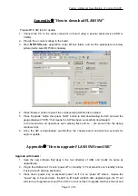
Download the latest release MT10_SW into the flash using MTK SW tool. See Appendix
n
“
How to download FLASH SW
”. Or upgrade the SW from USB port See Appendix
o
“How to


