Colour Television Chassis: M123A
35
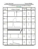
5. Faultfinding and Test Point with Waveform Diagram
5.1 Faultfinding
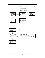
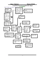
No raster +
B Voltage OK
Is the voltage
of in 25 of
IC201 3.3v
Is the resistance
to earth of pin25
if IC201 ok
No
Yes
Is the H-out
waveform at PIN
13 of IC201 OK?
Yes Check the waveform
at static working
point of Q401.
Yes
Check Q402
and LOT
No
Replace
IC201
NO
Yes
Replace IC201
Replace Q401
Is the output
voltage of IC401
9V?
Check R233,C231
and C233
yes
No
Figure3 No Raster, +B OK
No
No
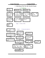
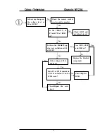
No picture, dense
noise dots
Is the antenna feed line
or the adapter broken
or unsoldered
?
Handing the antenna
fault
Yes
No
Is the signal at
Pin41, Pin42 of
IC201 ok?
Is the signal at IF
pin of the tuner
Is the signal at Pin
SCL, SDA of tuner ok?
No
Check signal at P57, P58, of
IC201 and replace the
abnormal relative circuit
Yes
Check EEPROM
Yes
Check/Replace
IC201
Yes
Is the supply
voltage of tuner
No
Check/Replace
power supply
circuit
Yes
Check/Replac
e Tuner
Yes
Check the relative
circuit of Q101,
Z101 etc
Figure 4 No Picture dense noise dots
Summary of Contents for CTR1042
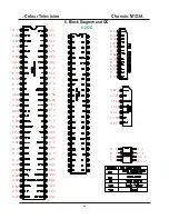
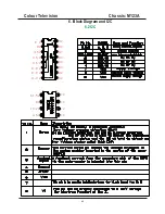
Page 41: ...Colour Television Chassis M123A 41 6 Block Diagram and I2C 6 1 Block Diagram...
Page 49: ...Colour Television Chassis M123A 49 7 Electrical Diagrams 7 10 CRT Panel...
Page 52: ...Colour Television Chassis M123A 52 8 PCB 8 1 Main PCB...
Page 53: ...Colour Television Chassis M123A 53 8 PCB 8 2 CRT PCB...
Page 54: ...Colour Television Chassis M123A 54 8 PCB 8 3 MPX PCB...
Page 55: ...Colour Television Chassis M123A 55 8 PCB 8 4 SIDE AV PCB...

