background image

2. Safety & Maintenance Instructions, Warnings and Notes

2.1 Safety Instructions For Repairs

2.2 Maintenance Instructions

      Safety regulations require that during a repair:
      --Due to the 'hot' parts of this chassis, the set must be connected to the AC power via an 
          isolation transformer.
      -- Safety components, indicated by the symbol _, should be replaced by components identical
          to the original ones.
      -- When replacing the CRT, safety goggles must be worn. Safety regulations require that after a
         repair, the set must be returned in its original condition. Pay particular attention to the
         following points:
     -- General repair instruction: as a strict precaution, we advise you to re-solder the solder 
        connections through  which the horizontal deflection current is flowing, in particular:
             ---   all pins of the line output transformer (LOT)
             ---   fly-back capacitor(s)
             ---   S-correction capacitor(s)
             ---    line output transistor
             ---    pins of the connector with wires to the deflection coil
             ---    other components through which the deflection current flows.

 * Note: This re-soldering is advised to prevent bad connections due to metal fatigue in solder
              connections and is therefore only necessary for television sets more than two years 
              Old.

     --  Route the wire trees and EHT cable correctly and secure them with the mounted cable clamps.
     --  Check the insulation of the AC power cord for external damage.
     --  Check the strain relief of the AC power cord for proper function, to prevent the cord from
          touching the CRT, hot components, or heat sinks.
     --  Check the electrical DC resistance between the AC plug and the secondary side (only for sets 
         that have an isolated power supply). Do this as follows:
         1. Unplug the AC power cord and connect a wire between the two pins of the AC plug.
         2. Turn on the main power switch (keep the AC power cord unplugged!).
         3. Measure the resistance value between the pins of the AC plug and the metal shielding of the
             tuner or the aerial connection of the set. The reading should be between 4.5 M

and 12 M

.

         4. Switch the TV OFF and remove the wire between the two pins of the AC plug.
              Check the cabinet for defects, to prevent the possibility of the customer touching any
             Internal parts.

       It is recommended to have a maintenance inspection carried out by qualified service 
  personnel. The interval depends on the usage conditions:
      ---  When the set is used under normal circumstances, for example in a living room, the
             recommended interval is hree to five years.
      ---  When the set is used in an environment with higher dust,grease or moisture levels, for
             example in a kitchen, the recommended interval is one year.
      ---  The maintenance inspection includes the following actions
            1. Perform the 'general repair instruction' noted above.
            2. Clean the power supply and deflection circuitry on the chassis.
            3. Clean the picture tube panel and the neck of the picture tube.

            Colour Television                                                 Chassis: M123A

4

Summary of Contents for CTR1042

Page 1: ...P Decoder Diagram A6 47 Video Source Switching Diagram A7 47 Side AV Diagram A8 48 Audio Amplifier Diagram A9 48 CRT Panel Diagram B 49 Transistor Test Voltage 49 Test point with Waveform Diagram 50 5...

Page 2: ...mperature 5 to 45 deg C Maximum humidity 90 Power consumption 80W Standby Power consumption 3W 1 1 2 Miscellaneous 1 2 Connections 1 2 1 Side Connections and Front Control IN1 AUDIO VIDEO S VIDEO L MO...

Page 3: ...3 1 3 Chassis Review 7 1 Power Supplier 7 2 Line Deflection 7 3 Frame Deflection 7 4 Tuner IF 7 5 MCU Video IF and Sound IF 7 6 BTSC Stereo SAP Decode 7 7 Video Source Switching MSP PANEL CRT PANEL M...

Page 4: ...ord for external damage Check the strain relief of the AC power cord for proper function to prevent the cord from touching the CRT hot components or heat sinks Check the electrical DC resistance betwe...

Page 5: ...picture tube Never replace modules or other components while the unit is switched ON When you align the set use plastic rather than metal tools This will prevent any short circuits and the danger of a...

Page 6: ...n page 12 If you have a Cable Box use the following steps Connect the Cable TV signal to the IN jack on the Cable Box Connect the separate coaxial cable to the OUT jack on the Cable Box and to the 75...

Page 7: ...ct it to the TV Go to step 2 If your antenna has flat twin lead wire 300 ohm you first need to attach the antenna wire to the screws on a 300 to 75 ohm adapter not Push the round end of the adapter or...

Page 8: ...o the TV s 75OHM ANTENNA INPUT jack ANTENNA INPUT jack on the TV If you connect it to the VCR choose TV channels at the VCR Connect it to the VCR if you want to record TV programming through VCR There...

Page 9: ...e sensor on the front of the TV when operating the TV with the remote control Battery Installation Remove the battery compartment lid on the rear of the remote Press in the tab then lift off the lid T...

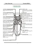
Page 10: ...if available with the TV programming MONO STEREO SAP and MONO SAP Details are on page 31 TV AV Button Press to select TV channels or the Audio Video IN channels AV1 S VIDEO AV2 or YUV CH channel Butt...

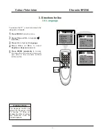
Page 11: ...remove the menu from the screen or menu will quit after a few seconds without further action E The language control only affects the language of the TV menus It does not change the other on screen te...

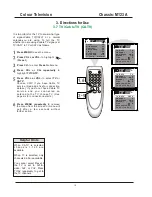
Page 12: ...OL or VOL to select TV or CATV Choose CATV if you have Cable TV service See page five for connection details If you do not have Cable TV service and you connected an antenna to the TV choose TV See pa...

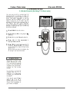
Page 13: ...repeatedly to highlight Auto search Press VOL or VOL to highlight Preset Press CH to enter Preset submenu Press VOL to start programming TV channels Press the VOL if you need to stop channel programmi...

Page 14: ...l Up TV TV CATV Auto search Add Erase Fine 0 F a v o r i t e l i s t Add TV TV CATV Auto search Manual Up Add Erase Fine 0 F a v o r i t e l i s t Add 2 Channel Manual Up CATV TV CATV Auto search Add...

Page 15: ...he menu from the screen or menu will quit after a few seconds without further action E Add Erase Fine 0 F a v o r i t e l i s t Add 2 Channel Manual Up TV TV Cable Auto search Add Erase Fine 0 Add 2 C...

Page 16: ...CH and CH buttons You cannot select Preset if the TV is set to AV1 S video AV2 or YUV Press TV AV repeatedly to get to the TV channels Helpful Hints Add Erase Fine 0 F a v o r i t e l i s t Add 12 Cha...

Page 17: ...und screen will appear if the TV is on a weak channel for example if the reception is very poor or if the station has gone off the air for the night After being on such a channel for 15 minutes the TV...

Page 18: ...ly adjust the TV s Brightness Color Contrast Sharpness and Tint Press SMART PICTURE on the r e m o t e c o n t r o l T h e c u r r e n t SmartPicture setting will appear on Press SMART PICTURE repeate...

Page 19: ...change the time quicky in 10 minute increments If the power fails you must reset the clock Helpful Hints Press M NU repeatedly to remove the menu from the screen or menu will quit after a few seconds...

Page 20: ...turn itself on Press CH or CH repeatedly to highlight Channel Press VOL or VOL to enter the channel number This will be the channel to which the TV turns on at the specified time Press CH or CH repea...

Page 21: ...eatedly to highlight 0 00 under the line of Off Time Press VOL or VOL to enter the Off time Hold down VOL or VOL to change the time quickly in 10 minutes increments This will be the time at which the...

Page 22: ...ful Hints Press MENU to see the menu Press VOL or VOL to highlight Feature Press CH to enter Feature submenus Press VOL or VOL to select the closed caption you want Off C1 C2 or C Mute C Mute sets the...

Page 23: ...you that trouble by turning itself off Press SLEEP The sleep display will appear on the screen Within five seconds press SLEEP to pick the amount of time in 10 minutes decrements before the TV will t...

Page 24: ...adult guardian It contains one or more of the following intense violence intense sexual situations strong coarse language or intensely suggestive dialog NC17 No children under the age of 17 will be ad...

Page 25: ...re Press CH to enter Feature submenus Press VOL on the remote and the CH button on the front of the TV at the same time The display asking you to Enter new code will appear on the screen Press M NU re...

Page 26: ...ion E Press CH or CH to highlight P Lock Press the Number buttons to enter your four digit code The P Lock setup menu appears on the screen and the MPAArating is highlighted Press OK to display MPAA r...

Page 27: ...onds without further action E Press CH or CH to highlight P Lock Press the Number buttons to enter your four digit code The P Lock setup menu appears on the screen Press OK to display the parental gui...

Page 28: ...rental Lock When ON all blocking censoring you have set is enabled When off all blocking is disabled BLOCK UNRATED All unrated programs based on Movies Ratings or TV Ratings will be blocked if this fe...

Page 29: ...ess CH or CH to highlight Child Lock Choose ON to disable all the buttons on the front of the TV Child Lock On will appear on the TV screen each time when you press the button on the front of the TV Y...

Page 30: ...ht Sound Press CH to enter Sound submenus Press CH or CH to highlight Smart Sound Press VOL or VOL to select Personal Voice Music or Theatre Press M NU repeatedly to remove the menu from the screen or...

Page 31: ...see the menu Press VOL or VOL to highlight Sound Press CH to enter Sound submenus Press CH or CH to highlight Bass Volume Treble or Balance Press VOL or VOL to adjust the option Press M NU repeatedly...

Page 32: ...oadcasting is available with the current TV program You can hear sound from the left and right speakers of the TV If the broadcast is not strong or clear stereo sound is not available Press the MTS bu...

Page 33: ...cover 2 Now pull the rear cover backward and remove it 4 2 Service Position Main Panel 4 3 Side I O Panel Removal 4 4 Rear Cover Mounting Before you mount the rear cover perform the following checks 1...

Page 34: ...801 shorted to earth Yes Cheek Replace Q801 Is D815 D818 OK Yes Check IC801 and the peripheral components Replace D815 D818 No No Figure 1 Fuse Blown No raster abnormal B Is the B resistance to earth...

Page 35: ...of IC401 9V Check R233 C231 and C233 yes No Figure3 No Raster B OK No No No picture dense noise dots Is the antenna feed line or the adapter broken or unsoldered Handing the antenna fault Yes No Is th...

Page 36: ...t the red probe to GND use the black probe to touch B of Q101 Are there interference particles flashing on the screen Yes Replace the Tuner No Is the voltage at P29 P36 of IC201 ok No Check and repair...

Page 37: ...e the power supply of IC1001 Then RESET NG Is the BUS ok Check IC201 and the relative circuit No No Check Replace Q1001 X1002 NG Is the waveform at P31 of IC201 ok Replace IC201 No Yes Replac e IC601...

Page 38: ...form of pin 14 of IC901 No Q905 and its peripheral circuit No Check Pin61 of IC201 and peripheral circuit Check the logic of Pin9 Pin10 of IC901 Yes Replace IC901 Yes AV has Picture TV hasn t Picture...

Page 39: ...of IC201 No Check the power supply of IC201 Are there H V flyback pulses at P12 of IC201 No No Check R408 R406 D404 C422 Yes Check Replace IC201 No Check the waveform at Pin57 Pin58 of IC201 No Yes Is...

Page 40: ...at P9 and P55 of IC201 ok Is there the 8MHz 5Vp p sine wave oscillations at P6 of IC201 Is the voltage at P5 of IC201 ok Have P5 of IC201 shorted to GND in an instant Can the IC201 work Check Repair t...

Page 41: ...Colour Television Chassis M123A 41 6 Block Diagram and I2C 6 1 Block Diagram...

Page 42: ...V 4 6V 3 5V 8 8V 4 9V 1 8V 4 3V 2 7V 2 1V 2 5V 4 5V 2 2V 4 8V 4 1V 0 V 0 V 0 V 4 4V 4 8V 1 8V 1 8V 2 5V 0 V 8 8V 2 6V 2 7V 2 5V 0 V 0 V 5 1V 5 1V 4 5V 4 2V 2 0V 0 V 4 7V 4 5V 5 0V 0 V 0 8V 0 4V 2 4V 1...

Page 43: ...Colour Television Chassis M123A 43 6 Block Diagram and I2C 6 2 I2C 0 V 0 V 61 5 V 0 V 0 V 5 V 4 5 V 0 V 0 V 0 V 0 V 0 V 0 V 0 V 0 V 0 9 V 0 9 V 0 9 V 13 2 V 4 5 V 4 5 V 4 5 V 0 V 9 V...

Page 44: ...Colour Television Chassis M123A 44 7 Electrical Diagrams 7 1 Power Supplier 7 Electrical Diagrams a 7 2 Line Deflection WF 1 WF 2 WF 3...

Page 45: ...Colour Television Chassis M123A 45 7 Electrical Diagrams 7 3 Frame Deflection 7 Electrical Diagrams 7 4 Tuner IF WF 4 WF 5 WF 6...

Page 46: ...Colour Television Chassis M123A 46 7 Electrical Diagrams 7 5 MCU Video IF and Sound IF WF 7 WF 8 WF 9 WF 10 WF 11...

Page 47: ...Colour Television Chassis M123A 47 7 Electrical Diagrams 7 6VBTSC Stereo SAP Decode 7 Electrical Diagrams 7 7Video Source Switching...

Page 48: ...Colour Television Chassis M123A 48 7 Electrical Diagrams 7 8 Side AV 7 Electrical Diagrams 7 9 Audio Amplifier...

Page 49: ...Colour Television Chassis M123A 49 7 Electrical Diagrams 7 10 CRT Panel...

Page 50: ...ng and Test point with Waveform Diagram Wave Shape NO Wave Shape Freq Vpp Period Hz WF 1 15 74 kHz 64 us 2 77 V WF 3 15 74 kHz 64 us 925 V WF 2 15 74 kHz 64 us 10 88 V WF 4 WF 5 WF 6 60 KHz 16 7 ms 13...

Page 51: ...11 Faultfinding and Test point with Waveform Diagram Wave Shape NO Wave Shape Freq Vpp Period WF 7 Hz 15 74 kHz 64 us 345 mV WF 8 15 74 kHz WF 9 15 74 kHz WF 10 60 KHz 16 7 ms 15 74 kHz 93 2 V 64 us 6...

Page 52: ...Colour Television Chassis M123A 52 8 PCB 8 1 Main PCB...

Page 53: ...Colour Television Chassis M123A 53 8 PCB 8 2 CRT PCB...

Page 54: ...Colour Television Chassis M123A 54 8 PCB 8 3 MPX PCB...

Page 55: ...Colour Television Chassis M123A 55 8 PCB 8 4 SIDE AV PCB...

Page 56: ...rtical output adjust the FOCUS on the flyback transformer to obtain the optimum focus 5 White balance adjustment 1 Apply the black and white pattern in normal status 2 Alignment of normal colour tempe...

Page 57: ...ur analyzer to X 279 Y 265 Separately set the brightness and contrast from min to max repeat the step 2 and 3 until the reading of the colour analyzer is correct Note Provided the production line is e...

Page 58: ...nu 19 directly by pressing digital button 1 9 0 notebook CAP Display Sleep Calendar System INS Favourite Return Picture Menu 1 Remote key 1 Item Remark RC R cut off setting GC G cut off setting BC B c...

Page 59: ...Remark ST3 50 Sharpness TV mode 3 58 system SV3 50 Sharpness AV mode 3 58 system SV4 50 Sharpness AV mode other system SVD 50 Sharpness DVD mode ASSH Asymmetric sharpness 04H bit 7 5 SHPX Maximum shar...

Page 60: ...zero or mute Bit 3 1 decreasing contrast when menu on Bit 4 1 OSD don t disappear automatically Bit 5 1 biological Bit 6 0 CH LOCK W O V CHIP Bit 7 When turn on 0 child lock off 1 child lock on OPTM2...

Page 61: ...OE5 Bit 0 English 1 yes 0 no Bit 1 French 1 yes 0 no Bit 2 Portuguese 1 yes 0 no Bit 3 Spanish 1 yes 0 no Bit 4 AV Color system PAL443 1 1 yes 0 no Bit 5 AV Color system NTSC443 1 1 yes 0 no Bit 6 AV...

Page 62: ...0 YDL 15H bit 2 0 40ns 240ns Bit 4 3 NTSC matrix 03H bit 7 6 N1 N2 DVD Bit 5C gamma 02H bit 7 color gamma on off Bit 6 P N ID 17H bit 4 PAL NTSC killer sensit Bit 7 FID 17H bit 3 Killer off ABL Bit 1...

Page 63: ...ature GD C G drive setting for cool color temperature BD C B drive setting for cool color temperature Menu 16 Remote key SYSTEM INS Item Remark RC W R cut off setting for warm color temperature GC W G...

Page 64: ...ENSI_ON SENSI_OFF Menu 21 no shortcut key Item Remark THEATER BAS Theater bass THEATER TRE Theater treble CONCERT BAS Concert bass CONCERT TRE Concert treble BROCAST BAS Brocast bass BROCAST TRE Broca...

Page 65: ...hus vertical frequency sync pulses under various systems canbe obtained TMPA8802 includes the vertical SW former sawtooth wave former and can control the gain and linear of SW sawtooth wave Therefore...

Page 66: ...d e g in LATAM and AP NTSC countries B TXT Blue teletext CC Closed Caption ComPair Computer aided rePair CRT Cathode Ray Tube or picture tube CSM Customer Service Mode CTI Colour Transient Improvement...

Page 67: ...4 5 MHz MSP Multi standard Sound Processor ITT sound decoder MUTE Mute Line NC Not Connected NICAM Near Instantaneous Compounded Audio Multiplexing This is a digital sound system mainly used in Europe...

Page 68: ...Memoire Colour system mainly used in France and East Europe Colour carriers 4 406250 MHz and 4 250000 MHz SIF Sound Intermediate Frequency SS Small Screen STBY Standby SVHS Super Video Home System SW...

Page 69: ...8 0E2 BATT TERMINAL 1 67 X31028 0E2 SPRING BATTERY 1 67 X31029 0E2 SPRING BATTERY 1 58 HS46F3 JUI1A INLAYREMOTEHANDSET 1 08 2170SG FCN ASS Y FRONTCABINET 1 02 GND021 XX0 ASS Y CRTGNDWIRE HOUSE 1 FORCR...

Page 70: ...90 0HG LINENIP 1 55 2170FC 3UA1K FRONTCABINET 1 58 2970SI 3UI INLAYSIDEAV 1 44 21RFLN SZ3A CRTA51QDX993X002 H 1 CRT01 08 2170SG MAN ASS Y MAINBD 1 07 457FF5 NX7 ALPSFSTUNERTEDH9 249A 1 TU101 10 0FR104...

Page 71: ...SC1815 YBX TRANSISTOR2SC1815Y 1 Q404 11 SC1815 YBX TRANSISTOR2SC1815Y 1 Q905 11 SC2482 0BX TRANSISTOR2SC2482 1 Q401 11 SC3779 DBX TRANSISTOR2SC3779D RFAMPL 1 Q101 11 SD2539 0AX TRANSISTOR2SD2539 HORI...

Page 72: ...5 1 R050 18 CB0103 JNX RES C F 10KOHM1 6W 5 1 R406 18 CB0104 JNX RES C F 100KOHM1 6W 5 1 R031 18 CB0121 JNX RES C F 120OHM1 6W 5 1 R227 18 CB0123 JNX RES C F 12kOHM1 6W 5 1 R212 18 CB0151 JNX RES C F...

Page 73: ...70OHM1 6W 5 1 R119 18 CB0471 JNX RES C F 470OHM1 6W 5 1 R208 18 CB0472 JNX RES C F 4 7kOHM1 6W 5 1 R016 18 CB0472 JNX RES C F 4 7kOHM1 6W 5 1 R015 18 CB0473 JNX RES C F 47KOHM1 6W 5 1 R216 18 CB0473 J...

Page 74: ...EC10UF16V 20 1 C907 25 BCB100 M1X CAP ELEC10UF16V 20 1 C603 25 BCB101 M1X CAP ELEC100UF16V 20 1 C016 25 BCB101 M1X CAP ELEC100UF16V 20 1 C240 25 BCB101 M1X CAP ELEC100UF16V 20 1 C605 25 BCB101 M1X CAP...

Page 75: ...R1000PF500V 10 B 1 C401 26 AIC102 KBX CAP CER1000PF500V 10 B 1 C404 26 AIC332 KBX CAP CER3300PF500V 10 B 1 C405 26 AIC391 KBX CAP CER390PF500V 10 B 1 C409 26 EBP102 KBX CAP CER1000PF50V 10 B 1 C112 26...

Page 76: ...1UF63V 5 1 C912 27 MBC104 J0X CAP M P E0 1UF63V 5 1 C910 27 MBC104 J0X CAP M P E0 1UF63V 5 1 C242 27 MBC104 J0X CAP M P E0 1UF63V 5 1 C309 27 PBA224 J0X CAP P E0 22UF63V 5 1 C305 27 PBC222 J0X CAP P E...

Page 77: ...M 1 J303 41 WJ0075 B00 WIREBAREJUMPER7 5MM 1 J024 41 WJ0075 B00 WIREBAREJUMPER7 5MM 1 J205 41 WJ0075 B00 WIREBAREJUMPER7 5MM 1 J206 41 WJ0075 B00 WIREBAREJUMPER7 5MM 1 J207 41 WJ0075 B00 WIREBAREJUMPE...

Page 78: ...BAREJUMPER12 5MM 1 J106 41 WJ0125 B00 WIREBAREJUMPER12 5MM 1 J924 41 WJ0125 B00 WIREBAREJUMPER12 5MM 1 R317 41 WJ0130 B00 WIREBAREJUMPER13MM 1 J204 41 WJ0130 B00 WIREBAREJUMPER13MM 1 J006 41 WJ0135 B0...

Page 79: ...HOLLOWRIVET1 6X3 0XL3 2 2 FORC421 66 343730 0B0 HOLLOWRIVET1 6X3 0XL3 2 2 FORC406B 66 343730 0B0 HOLLOWRIVET1 6X3 0XL3 2 9 FORFBT 66 382330 0B7 RIVET2 0X3 7X3 5 2 FORR402 66 382330 0B7 RIVET2 0X3 7X3...

Page 80: ...RES C F 1KOHM1 6W 5 1 R902 18 CB0102 JNX RES C F 1KOHM1 6W 5 1 R920 18 CB0102 JNX RES C F 1KOHM1 6W 5 1 R922 18 CB0820 JNX RES C F 82OHM1 6W 5 1 R905 18 CB0820 JNX RES C F 82OHM1 6W 5 1 R923 18 CB0820...

Page 81: ...560PF2KV 5 1 C402 41 WJ0060 B00 WIREBAREJUMPER6mm 1 R921 18 CB0103 JNX RES C F 10KOHM1 6W 5 1 R052 18 CB0472 JNX RES C F 4 7kOHM1 6W 5 1 R311 46 33079W 05X PINBASE 5TJC3 5A 1 P903 46 33079W 04X PINBAS...

Page 82: ...C802 13 44608P 40P ICMC44608P40 1 IC801 18 CB0102 JNX RES C F 1KOHM1 6W 5 1 R809 18 CB0103 JNX RES C F 10KOHM1 6W 5 1 R844 18 CB0332 JNX RES C F 3 3kOHM1 6W 5 1 R834 18 CB0392 JNX RES C F 3 9KOHM1 6W...

Page 83: ...1UF500V 10 B 1 C834 26 AIM103 KBX CAP CER0 01UF500V 10 B 1 C805 26 AKK221 KRX CAP CER220PF1KV 10 R 1 C833 26 AMK102 KBX CAP CER1000PF2KV 10 B 1 C815 26 APK222 ME4 CAP CER2200PF400VAC 20 E 1 C816 26 AP...

Page 84: ...REJUMPER19 5MM 1 J829 41 WJ0200 B00 WIREBAREJUMPER20MM 1 J830 46 10962W 02X PINBASE 2 TJC2 2A 1 P801 51 BC0243 0DH05 POWERCORDULPLUGW HOUSING 1 64 B30100 104 M CSCREWB3X10 1 FORQ801 66 20516X 0B0 FUSE...

Page 85: ...0250 AB2 S TSCREWB4X25AB 4 MTGFRONT REARCAB 63 F30100 BT3 S TSCREWF3X10BT BLACK 2 MTGRCAJACK REARCAB 54 114000 00X FELTTAPE 150mmX19mmX0 3mm 7 STICKONR CAB 62 301490 0UN SUPPORTER FORFBT 1 63 W30100 A...

Page 86: ...102 JNX RES C F 1KOHM1 6W 5 1 R1023 18 CB0103 JNX RES C F 10KOHM1 6W 5 1 R1003 18 CB0152 JNX RES C F 1 5kOHM1 6W 5 1 R1007 18 CB0332 JNX RES C F 3 3kOHM1 6W 5 1 R1005 18 CB0391 JNX RES C F 390OHM1 6W...

Page 87: ...C104 J0X CAP M P E0 1UF63V 5 1 C1037 27 MBC474 J0X CAP M P E0 47UF63V 5 1 C1039 34 R220J2 0EX COILPL 22UH 5 1 L1001 34 A100K0 0IX COILCHOKE10UH 10 1 J1002 34 A100K0 0IX COILCHOKE10UH 10 1 J1004 41 WJ0...

Page 88: ...18 CB0471 JNX RES C F 470OHM1 6W 5 1 R526 18 CB0471 JNX RES C F 470OHM1 6W 5 1 R527 18 CB0681 JNX RES C F 680OHM1 6W 5 1 R523 18 CB0751 JNX RES C F 750OHM1 6W 5 1 R503 18 CB0751 JNX RES C F 750OHM1 6W...

Page 89: ...P501 2 6 TO 1 5 41 WJ0075 B00 WIREBAREJUMPER7 5MM 1 J505 08 2170SG SIY ASS Y SIDEAVBD 1 11 SC1815 YBX TRANSISTOR2SC1815Y 1 Q951 18 CB0223 JNX RES C F 22kOHM1 6W 5 1 R951 18 CB0223 JNX RES C F 22kOHM1...

Reviews: