background image

T

T

T

T

T

T

GND

GND

T

T

T

GND

GND

GND

T

GND

GND

GND

T

GND

T

VIN

EN/EN#

NC

GND

VOUT

GND

T

GND

GND

GND

GND

GND

GND

GND

GND

GND

GND

GND

GND

GND

GND

GND

GND

GND

EN/EN#

OC

GND

OUT

IN

GND

GND

RX2+

GND1

RX2-

RX1+

GND2

RX1-

RX0+

GND3

RX0-

RXC+

GND4

RXC-

NC1

NC2

DDCCLK

DDCDA

GND5

VCC

HPD

GND

GND

GND

GND

GND

GND

T

.............

11-23-2010_14:02

...........

...

...

...

...

DD-MM

DD-MM

DD-MM

DD-MM

...

...

...

...

...

...

...

...

...

...

...

...

DD-MM-YY

......

ADDRESS1

ADDRESS2

ADDRESS3

TELEPHONE

NAME

Last modif

DESCRIPTION

DATE

DESIGNATION

DRAWN

CHECKED

ON:

BY:

BY:

ON:

PAGE:

OF  :

1

2

3

4

5

6

7

8

9

10

11

12

H

G

F

E

D

C

B

A

12

11

10

9

8

7

6

5

4

3

2

1

THIS DRAWING CANNOT BE COMMUNICATED TO UNAUTHORIZED PERSONS COPIED UNLES S PERMITTED IN WRITING

FORMAT DIN A1

H

G

F

E

D

C

A

Index-Lab

TCLNO:

SBU :

Last saved :

TCL

GND

RX2+

GND1

RX2-

RX1+

GND2

RX1-

RX0+

GND3

RX0-

RXC+

GND4

RXC-

NC1

NC2

DDCCLK

DDCDA

GND5

VCC

HPD

VCC-1

DNEG-1

DPOS-1

GND-1

MNT-HOLE1

MNT-HOLE2

GND

T

T

T

T

T

T

GND

MNT-HOLE1

MNT-HOLE2

GND

GND

LINE2

GND2

NC2

NC1

LINE3

NC4

LINE4

GND1

LINE1

NC3

T

T

(5)

(5)

(5)

(5)

(5)

(5)

(5)

(5)

(5)

(5)

(5)

(5)

(5)

(5)

(5)

(5)

(5)

(5)

(5)

(5)

(5)

(5)

(5)
(5)

Must be differential 100ohm

INTERNET

• WIFI

HDMI/MHL Prot1

HDMI Port2

(5)

(5)

USB2.0  Port

For MTK5507, reading EDID when HPD is High

When Power on or Standby and HDMI source is plugged in, HPD is High

When AC power OFF and HDMI sourc is plugged in, HPD is Low

WIFI

When use ESD Device, must delete 3.3pF on USB data line

UART_RX

UART_TX

UART_TX

UART_RX

R451

100R

C409

2P2

/NC

C408

2P2

/NC

R462

4K7

/NC

TXN

TXP

RXN

RXP

2

8

7

6

4

10

5

3

1

9

D402

AZ1045-04F

USB3_DP

USB3_DM

3

4

5

6

7

8

1

2

9

10

11

12

P401

RA406

22K

RA405

100R

USB_EN

C406

1000P

10

11

1

4

3

2

5

6

7

8

9

P408

RA404

470R

470R

RA403

2

1

NC/

PESD5V0S1BL

DA403

UART_TX

UART_RX

U1_DM

2

1

NC/

PESD5V0S1BL

DA402

2

1

NC/

PESD5V0S1BL

D428

USB1_5V

H_CEC

+5V

+5V

+5V

WIFI_GND

WAKE

WIFI_VCC

USB1D+

R410 2R2

WAKE-ON-LAN

CA400

0.01U

RA402

1K

RA401

4K7

0R

RA400

WAKE

3V3SB

GND

GND

+5V

DA401

BAS316 NC/

DA400

BAS316

WIFI_VCC

C407

0.1U

USB1D-

1

2

3

4

5

6

7

8

P402

_IN

9

10

8

7

6

5

4

3

1

2

ESD

13-ESD6V0-A4B0P6

D421

9

10

8

7

6

5

4

3

1

2

ESD

13-ESD6V0-A4B0P6

D419

9

10

8

7

6

5

4

3

1

2

ESD

13-ESD6V0-A4B0P6

D420

C418

10U

C417

470U

16V

1

2

3

4

5

6

P409

15

16

2

5

8

11

17

19

13

14

7

9

4

6

1

3

10

12

18

P405

H2_RX2-_IN

2

1

PESD5V0S1BL

D430

R446
47K

H1_ARC

C411

1U

R447
47K

R450

330R

R418

100R

R417
100R

GND

R411

220R

R409 2R2

C410

0.1U

WIFI_SW

10U

C467

10U

C447

H2_SDA_IN

R452 47K

H2_SCL_IN

S

D

G

Q414

MV65XP

H1_SDA_IN

H1_SCL_IN

R469

100R

R499

33R

R480
820R

R481
300K

R483

300K

R498

4R7

R497

4R7

R496

4R7

R495

4R7

R494

4R7

R493

4R7

R492

4R7

R491

4R7

R484

4R7

H_CEC

H_CEC

R416
10K

2

1

PESD5V0S1BL

D404

2

1

PESD5V0S1BL

D414

3V3SB

2

1

PESD5V0S1BL

D411

1

2

D408

PESD5V0S1BL

2

1

PESD5V0S1BL

D412

HDMI_CEC

H_CEC

R459

100R

R468
27K

D429

LL4148

4K7

R415

9

10

8

7

6

5

4

3

1

2

ESD

13-ESD6V0-A4B0P6

D422

MHL_SENSE

2

1

PESD5V0S1BL

D405

H1_SDA

15

16

2

5

8

11

17

19

13

14

7

9

4

6

1

3

10

12

18

P404

H1_SCL

RX1N

RX1P

TX1P

TX1N

R420

2R2

R412 2R2

R408

2R2

RXVP

RXVN

TXVN

R407 2R2

TXVP

H2_5V

R453 47K

R460

100R

MHL_SENSE

R404

75R

75R

R403

75R

R402

R401

75R

3V3SB

2

1

PESD5V0S1BL

D407

H1_HPD

1

2

D409

PESD5V0S1BL

1

2

D406

PESD5V0S1BL

1

2

D403

PESD5V0S1BL

C448

0.1U

4

3

2

1

5

U404

G524

VBUS

1

3

2

D413

BAT54A

R413

100R

E

C

B

BT3904

Q412

VBUS

H1_HPD

H1_HPD

VBUS

1

2

3

D410

BAT54C

H1_SDA

H2_HPD

MHL_PWR_EN

H2_HPD

HDMI2_HPD

R471

47K

0.1U

C445

C446

0.047U

R482

100R

H1_RX2-

R490

4R7

R489

4R7

R488

4R7

R487

4R7

R419

4R7

R486

4R7

R485

4R7

H2_CLK-

H2_RX0-

H2_RX1-

H2_RX2-

H2_SDA

H1_SCL

H1_RX1-

MHL+/

MHL-/H1_RX0-

100K

R474

16

15

14

13

12

11

10

9

8

7

6

5

4

3

2

1

TS8121CLF

U401

C403

0.01U

0.1U

C402

0.1U

C404

C405

0.01U

RXC

910R

R472

75R

R473

47K

R475

3V3SB

B

C

E

Q410

BT3904

E

C

B

BT3904

Q411

10K

R476

R479

47K

R478

20K

3V3SB

B

C

E

Q413

BT3904

3V3SB

H1_CLK-

H2_5V

H2_HPD

H2_SCL

H2_5V

MHL_SENSE

TXC

_IN

H1_RX2-_IN

_IN

H1_RX1-_IN

MHL+/_IN

MHL-/H1_RX0-_IN

_IN

H1_CLK-_IN

_IN

H2_RX1-_IN

H2_RXC-_IN

_IN

_IN

H2_RX0-_IN

VBUS

H1_HPD_CBUS

H1_SCL

H1_SDA

VBUS

H2_SCL

H2_SDA

C450

3P3

NC/

C449

3P3

NC/

2

1

NC/

PESD5V0S1BL

D425

2

1

NC/

PESD5V0S1BL

D426

2

1

NC/

PESD5V0S1BL

D427

R426 2R2

R425 2R2

USB1_D-

4

2

3

5

1

U403

RT9711A

R424

10K

F416

F415

GND

C416

10U

U2_DM

U1_DM

U2_DP

U1_DP

USB2_DM

USB2_DP

USB_5V

U2_DP

U2_DM

3V3

5V

H1_ARC_OUT

H1_ARC

H1_ARC

WOL

WIFI_ON

WAKE

WIFI_VCC

C419

0.1U

F456

F459

C452

3P3

NC/

C451

3P3

NC/

R449

2R2

R448

2R2

USB2_5V

USB2_D-

GNDU

U1_DP

USB_5V

USB1_DP

USB1_DM

TP

TN

RP

RN

TC

RC

TX1P

RX1N

RX1P

TX1N

TXC

RXC

Summary of Contents for L32D2930

Page 1: ...ion 3 Alignment Procedure 4 Block diagram 5 Scheme Diagram 6 Troubleshooting SORGH GUDZLQJ This m anual i s t he l atest at t he t ime of pr inting and doe s not include the modification which may be...

Page 2: ...ectric shock to the person The exclamation point within an equilateral triangle is intended to alert the user to the presence of important operating and maintenance servicing instructions in the liter...

Page 3: ...impact of any kind Be particularly careful not to damage the picture tube surface 9 Unplug this television set from the wall outlet before cleaning Do not use liquid cleaners or aerosol cleaners Use...

Page 4: ...ng conductors location of antenna discharge unit connection to grounding electrode and requirements for the grounding electrode 15 2 Note to CATV system installer Only for the television set with CATV...

Page 5: ...durein youroperatinginstructions do not attempt any further adjustment Unplug the set and call your dealer or service technician 22 Whenever the television set is damaged or fails or a distinct change...

Page 6: ...al Life Time Typ 30 000hrs Channels Edit For Channel renamed Color 16 7 Million 8bit Input Settings For Input source device choice Refresh Rate 60Hz Sleep Timer Yes System Update Yes T Link CEC Yes SI...

Page 7: ...40 feet High pcs 1180 Net Weight With Stand Kg 4 5kg Net Weight Without Stand Kg 4 4kg Gross Weight With Packaging Kg 6 0kg VESA Mounting Dimensions LxH mm 100X100 Operation Manual English Default Wa...

Page 8: ...00 Max 500mA MAINPOWER 12V 3V3SB 3V3 400mA 5V 12V_AMP Max 2A For MT5531 Standby Mode AS1117 33B 1A max AS1117 33B 1A max 12V POWER LED IR KEY TPS56528 Max 5A PANEL_VCC 12V 600mA max SOC AMP AD82587D E...

Page 9: ...ification for MT56EP1 Series v0 01 160825 docx Page 1 of 25 TCL World Wide R D FPD CENTER Test Alignment Specification TAS forMT565EP1 LA Series Version0 01 PREPARED BY DATE 2017 05 05 CHECKED BY DATE...

Page 10: ...nformation contained in this document is proprietary to TCL HZ FPD lab and shall not be disclosed by the recipient to third persons without the written permission of the team leader or GP of R D Revis...

Page 11: ...p 720p up to 1080i p compliant v1 4 with HDCP 2 HDMI 1 4 VGA VGA DVI audio CMP YPrPb can support from 480i up to 1080p audio Side AV or Back AV CVBS audio 1 Side Audio OUT 1 USB thumb drive 2 USB2 0 P...

Page 12: ...B V8 XX56XX LF1VXXX HDMI SWITCH EDID BIN image HDMI EDID and HDCP Embedded in main chip Include in main SW MEMC software BIN image N A EEPROM N A Manufacturing Connectors Pinout ISP UART P15 Pin1 NC P...

Page 13: ...relevant block diagram and circuit diagram and make sure that no serious issue or mistake can destroy the board For example the output of DC DC and LDO should not be shorted to ground Supply a suited...

Page 14: ...th itsUSB port well connected to suitable UART device or an IR emitter device correctly facing up TV see below Product Assembly section 2 0 how to activate Factory key The UART parser engine is enable...

Page 15: ...1280x720 2D Static Picture 1920x1080 1 Frequency Range full band 2 Standard PAL NTSC N M 3 ISDB T SPDIF optical Audio Amplifier PCM or Dolby D CMP via mini jack adaptor YPrPb Audio Chroma QuantumData...

Page 16: ...eded to check whether the HDCP key has been well set by connecting suitable generator 1 9 CI Key Upgrade Activation and Test See Appendix How to upgradeCI Key using USB 1 10 LAN and WLAN Test MAC addr...

Page 17: ...test can be done by connecting DHCP server to TV s RJ45 and check that IP subnet mask DNS addresses are visible on User menu Network Internet connection On IP settings More in depth test can be perfor...

Page 18: ...lowing TCL standard and practices it s required minimum 15min of Warm Up that can be considered as Burn In Additional Aging for White Balance alignment is no more necessary due to consistent Picture P...

Page 19: ...ted at 70IRE Targets and Tolerances for all inputs According tocompanyuniform LED color temperature standard of panel The measured and adjustable parameters should be mainly x y coordinates The White...

Page 20: ...ned and prepared channels maps volume picture presets user can prepare golden clone image that can be copied on demand to all further TV production lot of same TV To access cloning function you can se...

Page 21: ...Factory menu Reset Shop then pressing RCU OK key Other faster methods via UART IR commands are available on enclosed SIACP requirements rev v5 4 Note A password might be required in case of Parental C...

Page 22: ...ther version of the program Download the SW Package V8 NT66701 LM1Rxxx bin from FTP and rename the file V8 NT66701 LM1Rxxx bin to NT_FRC bin Copy the SW Bin image NT_FRC bin into USB stick pen drive r...

Page 23: ...or go to Factory menu Other OAD update and then press RCU OK key OAD will start automatically and several pop up messages such as scanning searching downloading and flashing will be skipped acknowledg...

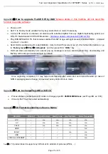
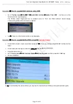
Page 24: ...driver root path Copy corresponding key files into CIKEY folder Under CIKEY folder create a new folder named backup once the CI key is overwritten the matching key file will be moved to this folder Pl...

Page 25: ...nding address like onto below snapshot Note There is no this function which is only displaying Appendix How to upgradeNetflex ESN using USB already finished Under USB root path create a new folder nam...

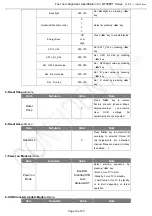
Page 26: ...bmenu Item Sub item Value Note White Balance Source HDMI TV AV CMP Cannot be Selected Color Temperature Standard Warm Cool Select Tone by pressing key R Gain 000 255 Set R Gain by pressing key 128 127...

Page 27: ...ssing key 5 Reset Shopsubmenu Item Sub item Value Note Reset Shop Press OK key to remove Factory presets channel Maps bargraphcontext and restore User OOB settings All adjustments are not impacted 6 R...

Page 28: ...pgrade ESN Key 0 Othersubmenu Item Sub item Value Note WatchDog Watch dog ON OFF Select watch dog ON or OFF by pressing key Upgrade CI Credential Update CI Credential Press OK key to active CI key Upd...

Page 29: ...o your LAN by connecting the LAN port on your TV to an IP Sharer which is connected to an external modem Use Cat5 cable for the connection 3 Depending on how your network is configured you may be able...

Page 30: ...t then press OK to check theInternet connectivity If failed follow below steps toensure connectivity Select User menu Network IP settings then press OK to enter into IP settings submenu Set Address ty...

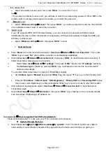
Page 31: ...Select Download software will be download automatically The download progress will be shown in the lower right corner note Please follow the instructions on TV if download or update failed And you can...

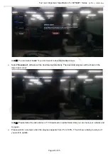
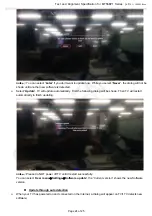
Page 32: ...ct Update TV will update automatically First the following dialog will be shown Then TV will restart automatically to finish updating note 22 Please do NOT power off TV until it restart successfully Y...

Page 33: ...25 note 23 You can select Later if you don t want to download software and if you select the Never the dialog will not be shown until another new software is detected Select Download and TV will downl...

Page 34: ...M R LED C_3V3SB 0 1U C111 C051 10U C050 10U CDB0 10U 10K RA134 DA130 BAS316 3V3SB 3V3SB DA101 5V6 NC DA100 BAS316 NC RA103 10K R052 5K6 R051 330R R050 27K C054 1000P 0R RA113 RA115 10K 3V3SB R130 820R...

Page 35: ...3 24 UT3 SI2183 TUNER_VCC DEMO_1V2 DEMO_1V2 DEMO_1V2 6 11 10 7 8 1 3 2 4 5 9 TUN2 AGC XT16M 16M 16PF CT22 22P CT21 22P RT35 1K AGC SDA SCL RT21 100R RT19 1K RT18 1K 100R RT22 1V2_DEMO CT100 0 022U TUN...

Page 36: ...UTHORIZED PERSONS COPIED UNLES S PERMITTED IN WRITING 4 5 6 7 8 F E D C B A 8 7 6 5 4 3 2 1 F E D C B FORMAT DIN A3 VCC GND IN GND1 GND2 TX LED IC DRIVE SPDIF CLOSE TO SOC C322 0 1U C321 47P SPDIF_OUT...

Page 37: ...0 12 18 P405 H2_RX2 _IN 2 1 PESD5V0S1BL D430 R446 47K H1_ARC C411 1U R447 47K R450 330R R418 100R R417 100R GND R411 220R R409 2R2 C410 0 1U WIFI_SW 10U C467 10U C447 H2_SDA_IN R452 47K H2_SCL_IN S D...

Page 38: ...7 7 7 7 7 7 3 0 0 0 0 0 Crystal oscillator port SOC VEDIO SOC AUDIO Bottom SIDE SOC POWER SOC EMMC SOC CI SOC RESET SOC USB SOC Ethernet STRAPPING OPCTRL3 eMMC pins share pins w s NAND ICE moce 24M RO...

Page 39: ...7 N7 P3 N2 P8 P2 R8 R2 T8 R3 M2 N8 M3 J7 K9 E7 D3 E3 F7 F2 F8 H3 H8 G2 H7 F3 C7 D7 C3 C8 C2 A7 A2 B8 A3 J1 J9 L1 L9 M7 T3 T7 K1 B2 D9 G7 K2 K8 N1 N9 R1 R9 A1 A8 C1 C9 D2 E9 F1 H2 H9 M8 H1 A9 E1 T9 B3...

Page 40: ...5 5 5 5 5 5 5 5 5 EMMC W6 W5 K2 H3 H4 H5 J2 J3 J4 J5 J6 T5 H6 U5 U9 T10 N5 M6 AA3 AA5 Y4 W4 K6 K4 M7 P5 R10 U8 Y2 Y5 AA4 AA6 UF01 CPP THGBM5G6A2JBH2H C711 1U C710 10U C704 10U 1V8 3V3 C712 0 1U C713...

Page 41: ...RCIN SDA SCL RESET VSS RB VDDRB VDDLB LB GNDL NC2 VDDLA LA VDD SA0 MCLK BCLK 5 5 5 5 5 5 1 5 7 7 Close to SOC AD82587D_12V 9 9 1000P C817 C816 1000P C822 1000P 1000P C823 C821 0 22U 0 22U C815 13 14 1...

Page 42: ...D Panel use P902 and NC P901 2 For FHD Panel 60HZ use P901 and NC P902 4 LG_DIM_OUT are PWM port 5 DIM_SW_OUT is from DIM switch circuit 6 IIC option for panel 7 Default value in this diagram is for p...

Page 43: ...1 R1030 75R 1 4 2 3 P1005 HD_V HD_L HD_R HD1_R 1 4 2 5 3 6 P1004 HD_GND 47P C1020 OUT_GND OUT_R OUT_L C1057 470P 470P C1056 L1051 600R L1050 600R F1051 F1050 1 2 PESD5V0S1BL D1056 2 1 D1055 PESD5V0S1B...

Page 44: ...43 1 2 47R PC28 2 1 NC L1 L2 3 4 2 PL2 1 L1 L2 PL1 1 3 4 2 PP1 1 2 PCY1A 2 1 PCY1 2 1 PCY2A 2 1 PCY2 2 1 PCY3 2 1 PCY3A 2 1 T 1 Z27V GND VLED 1 2 PC27 NC T T 1 2 0 1U PC12 GND 1 ZGND1 1 Z12V P N 25V 4...

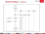
Page 45: ...Trouble Shooting No Picture 41...

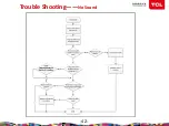
Page 46: ...Trouble Shooting No Sound 42...

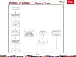
Page 47: ...Trouble Shooting Abnormal Picture 43...

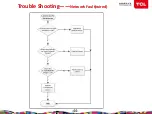
Page 48: ...Trouble Shooting Network Fault wired 44...

Page 49: ...Trouble Shooting Network Fault wireless 45...

Page 50: ......

Reviews: