background image

11.

Do not use this television set near water ... for example, near a bathtub, washbowl, kitchen sink, or laundry tub, in a

wet basement, or near a swimming pool, etc.

Never expose the set to rain or water. If the set has been exposed to rain or water, unplug the set from the wall

outlet and refer servicing to qualified service personnel.

12. Choose a place where light (artificial or sunlight) does not shine directly on the screen.

13. Avoid dusty places, since piling up of dust inside TV chassis may cause failure of the set when high humidity persists.

14. The set has slots, or openings in the cabinet for ventilation purposes, to provide reliable operation of the receiver, to

protect it from overheating. These openings must not be blocked or covered.

Never cover the slots or openings with cloth or other material.
Never block the bottom ventilation slots of the set by placing it on a bed, sofa, rug, etc.
Never place the set near or over a radiator or heat register.
Never place the set in

enclosure, unless proper ventilation is provided.

15.1. If an outside antenna is connected to the television set, be sure the antenna system is grounded so as to provide some

protection against voltage surges and built up static charges, Section 810 of the National Electrical Code, NFPA No.
70-1975, provides information with respect to proper grounding of the mast and supporting structure, grounding of the
lead-in wire to an antenna discharge unit, size of grounding conductors, location of antenna discharge unit, connection
to grounding electrode, and requirements for the grounding electrode.

15.2. Note to CATV system installer : (Only for the television set with CATV reception)

This reminder is provided to call the CATV system

attention to Article 820-40 of the NEC that provides

guidelines for proper grounding and, in particular, specifies that the cable ground shall be connected to the grounding
system of the building, as close to the point of cable entry as practical.

16.

An outside antenna system should not be located in the vicinity of overhead power lines or other electric lights or power
circuits, or where it can fall into such power lines or circuits. When installing an outside antenna system, extreme care
should be taken to keep from touching such power lines or circuits as contact with them might be fatal.

17.

For added protection for this television set during a lightning storm, or when it is left unattended and unused for long
periods of time, unplug it from the wall outlet and disconnect the antenna. This will prevent damage due to lightning
and power-line surges.

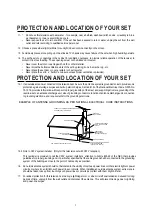
ANTENNA

LEAD- IN WIRE

ANTENNA DISCHARGE

UNIT (NEC SECTION

810-20)

GROUNDING

CONDUCTORS

(NEC SECTION810-21)

GROUND CLAMPS

POWER SERVICE GROUNDING

ELECTRODE SYSTEM

(NEC ART 250. PART H)

ELECTRIC SERVICE

EQUIPMENT

GROUND CLAMP

NEC-NATIONAL ELECTRICAL CODE

EXAMPLE OF ANTENNA GROUNDING AS PER
NATIONAL ELECTRICAL CODE

EXAMPLE OF ANTENNA GROUNDING AS PER NATIONAL ELECTRICAL CODE INSTRUCTIONS

a built-in

installer s

4

SCHNEIDER ELECTRONICS GMBH-GERMANY

PROTECTION AND LOCATION OF YOUR SET

PROTECTION AND LOCATION OF YOUR SET

4

Summary of Contents for LCD20V6AT

Page 1: ... 8 4 Alignment Procedure 14 5 Circuit Block Diagram 15 6 Schematic Diagram 18 7 Explode View Diagram 27 This manual is the latest at the time of printing and does not include the modification which may be made after the printing by the constant improvement of product ...

Page 2: ...lectric shock to the person The exclamation point within an equilateral triangle is intended to alert the user to the presence of important operating and maintenance servicing instructions in the literature accompanying the appliance CAUTION Use of controls adjustments or procedures other than those specified herein may result in hazardous radiation exposure CA U T ION RISK RISK OF ELECTRI ELECTRI...

Page 3: ...o impact of any kind Be particularly careful not to damage the picture tube surface 9 Unplug this television set from the wall outlet before cleaning Do not use liquid cleaners or aerosol cleaners Use a damp cloth for cleaning 10 1 Do not place this television set on an unstable cart stand or table The television set may fall causing serious injury to a child or an adult and serious damage to the ...

Page 4: ...ing conductors location of antenna discharge unit connection to grounding electrode and requirements for the grounding electrode 15 2 Note to CATV system installer Only for the television set with CATV reception This reminder is provided to call the CATV system attention to Article 820 40 of the NEC that provides guidelines for proper grounding and in particular specifies that the cable ground sha...

Page 5: ...edurein youroperatinginstructions do not attempt any further adjustment Unplug the set and call your dealer or service technician 22 Whenever the television set is damaged or fails or a distinct change in performance indicates a need for service unplug the set and have it checked by a professional service technician 23 It is normal for some TV sets to make occasional snapping or popping sounds par...

Page 6: ...768 1920 1080 Other Max Resolution H V 640 480 800 600 1024 768 1400 1050 1600 1200 1280 800 1280 854 1920 1200 Other Screen Parameter HDTV SDTV p 1920 1080i 1920 1080p 1920 1125i 1440 1080i 1280 720P 576P 720 480p Other Color System TV PAL DK PAL I NTSC M PAL BG PAL N PAL M SECAM SECAM L Other AV NTSC4 43 NTSC3 58 PAL SECAM Other Nicam NICAM MTS FM FM German Stereo BTSC SAP Other Program Program ...

Page 7: ...int H V position YCbCr Other Certification CCC CE UL CUL FCC FDA CB RoHS Other Power Supply Max Power Consumption W 55W Voltage V 110 240V Standby Power Consumption W 6W Switch on off Auto stand by Timer 5 Min Other Time On Accessories Remote Control Stand Optional Scart Cord m Bracket Optional Bracket Accessories Optional Power Supply Cord Antenna 1 8 m Speakers Optional VGA line Type Other Adapt...

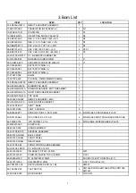
Page 8: ...QBATTDOOR REMOTEHANDSET 1 55 HS36QT 0HA1H TOP CASE 1 56 399030 0HC5Z REMOTE HANDSET LENS 1 58 HS36Q0 FUI1A INLAY REMOTE HANDSET 1 T8 JV6TRT BSY ASS Y BASE 1 59 100010 000 FOOT CUSHION 8 63 B30080 BT3 SCREW BT BID 3 X 8 STL BZN 10 MTG BASE COVER SEEEL PLATE 63 B30120 AB2 S T SCREW B 3 X 12 AB 2 MTG BASE FRONT CAB BASE REAR CAB 64 F40080 103 M C SCREW F 4 X 8 9 MTG HINGE ASSEM SEEEL PLATE 67 M80437 ...

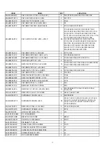
Page 9: ...B DECORATE BAR 1 T8 JV6TRT PAN PACKING ASSEMBLY 1 49 204260 BAT 7 BATT UM4 R03P SIZE AAA 2 51 PC0220 0ZU08 POWER CORD 1 54 LCPVC1 001 PROTECT INLAY 1 81 ADT125 201 ADAPTER SAWA 02 520 1 T8 JV6TRT PANZ ASS Y ARFPACKINGPARTS 1 T8 JV6TRT RCN REAR CABINET ASSEMBLY 1 63 B30120 AB3 S T SCREW B 3 0 X 12 4 MTG REAR CAB FRONT CAB 64 F40080 103 M C SCREW F 4 X 8 6 MIG REAR CAB HINGE ASSEMBLY T8 JV6TRT RCNZ ...

Page 10: ...RES 1 5K OHM 1 10W 5 0603 1 R128 19 AB0202 JTX SMD RES 2K OHM 1 10W 5 0603 1 R79 19 AB0220 JTX SMD RES 22 OHM 1 10W 0603 9 R7 R5 R93 R92 R94 R95 R137 R23 R27 19 AB0222 JTX RES SMD 2 2K OHM 1 10W 0603 7 R133 R134 R126 R125 R123 R131 R132 19 AB0223 JTX SMD RES 22K OHM 1 10W 5 0603 7 R47 R46 R42 R41 R26 R24 R136 19 AB0271 JTX SMD RES 270 OHM 1 10W 5 0603 1 R53 19 AB0272 JTX RES SMD 2 7K OHM 1 10W 060...

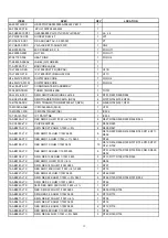
Page 11: ...8 AB0470 JCX CAP SMD 47PF 50V 5 0603 1 C76 28 AB0479 CCX SMD CAP 4 7 PF 50V 0 25PF 5 C119 C126 C157 C147 C140 28 AB0509 CCX CAP SMD 5PF 50V 0 25PF 2 C58 C59 28 AB0561 JCX SMD CAP 560 PF 50VDC 5 0603 1 C166 28 AB0682 KBX SMD CAP 6800PF 50VDC 10 1 C172 28 AB0683 ZFX SMD CAP 68NF 50V 80 20 0603 1 C174 28 AB0809 CCX CAP SMD 8PF 50V 0 25PF 1 C63 28 BB0101 JCX SMD CAP 100 PF 50V C 0805 1 C89 28 BB0104 Z...

Page 12: ... 6 R527 R706 R539 R535 R534 R538 19 CC0000 JTX CHIP RESISTOR 2 D502 R525 19 AB0273 JTX SMD RES 27K OHM 1 10W 5 2 R528 R547 19 AB0101 JTX RES SMD 100 OHM 1 10W 0603 9 R515 R507 R530 R516 R508 R740 R714 R711 R506 19 AB0102 FTX RES SMD 1K OHM 1 10W 1 0603 1 R748 19 AB0102 JTX RES SMD 1K OHM 1 10W 0603 10 R512 R514 R509 R729 R727 R734 R735 R737 R741 R752 19 AB0103 JTX RES SMD 10K OHM 1 10W 0603 9 R731...

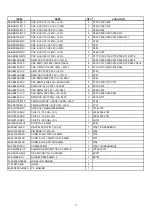
Page 13: ...1 C543 28 AB0224 ZFX CAP SMD 0 22UF 50V 80 20 0603 4 C722 C725 C727 C707 28 AB0339 CCX SMD CAP 50V 3 3PF 0 25PF 2 C518 C519 28 AB0470 JCX CAP SMD 47PF 50V 5 0603 2 C508 C507 28 AB0471 JCX CAP SMD 470PF 50V 5 0603 4 C501 C502 C529 C503 28 AB0560 JCX SMD CAP 56 PF 50V 5 0603 2 C515 C517 28 DC0107 MTX TANTALUM CAP 100 UF 16VDC 20 1 C706 28 XC0106 MTX TANTALUM CAP 10 UF 16V 20 1 C713 33 KLN102 NTX SMD...

Page 14: ...ory Mode and select Auto Adjust to calibrate ADC to standard state 5 Make sure the color is OK in these modes 640 400 60Hz 720 400 60Hz 640 480 60Hz 800 600 60Hz 1024X768 60HZ 2 Auto adjustment of White Balance 1 Auto adjustment in VGA HDTV mode Required equipment Color analyzer Chroma7120 Specific series port interface HDTV signal generator A Input 720p Full White signal from Chroma7120 B Switch ...

Page 15: ...x 284 15 y 299 15 c Warm color temperature select warm in factory menu and revise R G B gain value until x 305 15 y 320 15 2 AV TV mode A Select AV mode then press PRESETS button to select Standard picture mode B Input the Gray Scales signal and adjust Blacklight in factory menu until the second dark scale is just visible C Input H 2 White Reference signal then adjust white balance The method is s...

Page 16: ...M Only WARM STANDARD and COOL need to be adjusted in White Balance adjustment Item Default Description Brightness 50 Brightness Contrast 50 Contrast RED Red Gain GREEN Green Gain BLUE Blue Gain Y The brightness of auto adj AUTO Auto adjustment 5 Advanced Setting Item Default Description Factory Mode 0 To set the method of entering the Factory Mode Power Mode 1 To set the state of the unit after po...

Page 17: ...DIAGRAM I2C BUS L CVBS SIF R GM2221 LVDS OR TTL LCD PANEL BUS FLASH 39SF020A SWITCH PI5V330Q R G B Y U V A D TVP5147 CVBS Y C TUNER PHILIPS 1316 MSP3410 AMPLIFIER 1517 ADAPTER AC INPUT 12V DC R F 17 ...

Page 18: ...GM21 LCD TV__for EU SCHEMATIC 03 GM2221 2 04 SPI RESET KEYPAD 6 Approval SHEET 3 4 Date CONTENTS 1 7 05 LVDS_ Out 06 TTL_ Out 8 01 Contents 07 Power 08 VIDEO DECODER CHY 04 05 17 040108 chy GM21 B 1 9 Tuesday October 18 2005 Title Size Document Number Rev Date Sheet of 18 ...

Page 19: ... R18 100R C8 0 01uF Q3 BC847c 1 2 3 R30 10K R31 10K C4 10uF Q6 BC847c 1 2 3 R33 10k C13 10uF 16V 1 2 C5 0 01uF R19 82 R49 82 R24 22k C6 0 01uF R10 100R C220 0 1UF R 75 R39 84 5 1 R35 10k R36 82 D7 BAV99 1 2 3 C2 0 1uF Q BC847c 1 2 3 Q5 BC847c 1 2 3 D8 BAV99 1 2 3 R20 82 C11 10uF 16V 1 2 R21 82 C10 0 01uF R27 20R 1 R 82 R40 84 5 1 A1 A2 C BAT54C D5 R25 47R 1 R12 10K R14 10K R46 22k C15 10uF 16V 1 2...

Page 20: ... 97 140 180 163 165 136 155 48 47 87 86 66 65 33 34 62 59 61 60 58 57 63 64 46 45 44 43 38 37 55 56 32 31 30 29 22 21 49 54 18 17 16 15 14 13 19 20 167 70 135 27 40 113 120 125 130 134 141 145 7 6 95 184 183 191 206 139 179 177 39 168 156 131 127 146 81 82 83 84 85 88 89 90 91 138 10 102 103 106 107 108 109 110 111 112 52 53 104 105 157 158 159 160 161 162 173 174 175 176 RED RED GREEN GREEN BLUE ...

Page 21: ..._IN1 MCSCL MCSDA LED Audio_InR2 Audio_InL2 Audio_OutR2 Audio_OutL2 SWICH1 SWICH3 CVBS2 CVBS1 SVIDEO_Y SVIDEO_C AMP_MUTE RET_OTHER MCSCL MCSDA Vin2 Vout2 TELE_INR 5V GND 5V GND GND GND 12V 9V 5V GND 9V GND 5V GND GND C68 0 1uF J3 CON15 1 2 3 4 5 6 7 8 9 10 11 12 13 14 15 R77 4K7 C69 0 1uF J CON2 1 2 J CON3 1 2 3 C64 220pF J6 CON6 1 2 3 4 5 6 U7 24LC16B 1 2 3 4 5 6 7 8 A0 A1 A2 VSS SI SCK WP VCC R76...

Page 22: ... LV_E5 ER4 LV_E9 ER0 TXE3 LV_E8 ER1 LV_E4 ER5 TXE1 TXE0 LV_E1 EG0 LV_E3 ER6 LV_E7 ER2 TXE1 LV_E2 ER7 LV_E0 EG1 TXE0 TXEC PBIAS BKLT_EN BKLT_EN LV_E 0 9 LV_O 0 9 PWM0 GND GND 5V GND GND PANEL_POWER GND 5V 3 3V_DVDD PANEL_POWER GND 5V GND 12V GND 12V 5V GND GND GND GND L6 31R FB L8 31R FB L7 31R FB R80 470R Q9 MMBT3904L 3 1 2 R84 1K R83 4k7 Q7 MMBT3904L 3 1 2 F1 33R FB TP15 R82 1K C75 22uF 16V C72 0...

Page 23: ...ER0 EG7 EG0 HS ER5 CLK ER0 LV_E2 LV_E0 LV_E1 LV_E8 LV_E5 LV_E7 LV_E3 ER5 LV_E6 ER3 ER2 ER7 LV_E4 ER1 ER6 LV_E9 ER4 CLK LV_E 0 9 LV_O 0 9 PD 20 23 GND GND PANEL_POWER PANEL_POWER GND R95 22R RN5 22Rx4 8 7 6 5 4 3 2 1 RN6 22Rx4 8 7 6 5 4 3 2 1 RN3 22Rx4 8 7 6 5 4 3 2 1 RN2 22Rx4 8 7 6 5 4 3 2 1 R93 22R RN1 22Rx4 8 7 6 5 4 3 2 1 R94 22R J10 87089 40 1 3 5 7 9 11 13 15 17 19 21 23 25 27 29 31 33 35 37...

Page 24: ... FB C102 22uF 16V C105 100uF 16V L14 33R FB C84 0 1uF C96 0 1uF U10 lt1084 3 3V 1 3 2 4 GND ADJ VIN VOUT TAB C101 0 1uF C97 100uF 16V 10V U9 LM2596S 5 0 1 3 2 4 5 6 VIN GND VOUT ADJ ON TAB R98 2k2 D12 1N4001 C94 100uF 16V 10V R96 100 C88 0 1u L12 33R FB C89 100P C107 0 1uF L19 33R FB C108 22uF 16V D11 1N4001 L20 33R FB L25 33R FB L29 33R FB U12LT1117 3 3V Sot223 1 3 2 4 GND ADJ VIN VOUT TAB L18 33...

Page 25: ...F R 0 R99 100R C139 0 1uF C164 330pF C163 0 1uF C150 0 1uF L49 2 7uH R104 NC C 10P R100 100R C157 4 7pF L35 2 7uH C118 33pF R114 22R R111 75R 1 L31 33R FB TP16 C136 0 1uF L33 33R FB L37 2 7uH C135 0 1uF RN7 22Rx4 1 2 3 4 5 6 7 8 J12 CON10 1 2 3 4 5 6 7 8 9 10 TP17 R112120 C149 330pF C141 330pF C224 330pF TP18 C228 330pF C226 330pF C140 4 7pF C227 330pF C134 0 1uF C229 330pF C117 33pF R 0 C 10P C12...

Page 26: ...731 10K C519 3 3P R737 1k C533 3u3 25v R729 1K R507 10k L703 100UH R715 3K3 R740 100 C555 NC R736 82 C703 470U 16V R508 100 D504 1N4148 R730 10K L506 22uH J703 CON2 1 2 R711 100 R535 0 Q701 3904 R520 1K R532 103 C726 22u 50v C709 22U 16V R529 NC LN701 220UH R539 0 C535 10u 25v R533 103 C508 47P R516 100 R776 NS R506 100 R705 470 R714 100 R517 1K IC502 MSP3410G 1 2 3 4 5 6 7 8 9 10 11 12 13 16 48 4...

Page 27: ...27 ...

Reviews: