background image

5

5

4

4

3

3

2

2

1

1

D

D

C

C

B

B

A

A

V+

V-

MENU

AV/TV

CH+

CH-

VCC5
REMOTE
REF
LED

POWER

SPEAKER R

SPEAKER L

KEY BOARD

B

A

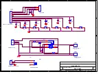
 H6L LCD-TV

11

14

Wednesday, October 13, 2004

Title

Size

Document Number

Rev

Date:

Sheet

of

CN504

HDR1X2 2.54mm Header

1

2

3

1

2

3

S504

PUSHBUTTON

S502

PUSHBUTTON

CN501

HDR1X11 SMT RT2mm

1

2

3

4

5

6

7

8

9

10

11

C509

0.01uF

CN503

HDR1X4 2.54mm 

1

2

3

4

L

GND

GND

R

C504

0.1uF

S501

PUSHBUTTON

C506

0.01uF

C510

0.01uF

CN506

HDR1X2 2.54mm 

1

2

L

GND

C505

0.1uF

S505

PUSHBUTTON

CN507

HDR1X2 2.54mm 

1

2

R

GND

C511

0.01uF

J508

PHONEJACK STEREO

1

2

3

4

5

6

7

8

9

R502

470 

C507

0.01uF

S503

PUSHBUTTON

CN502

4PIN2.0MM

1

2

3

4

S507

SW PUSHBUTTON

1

2

3

S506

PUSHBUTTON

C512

0.01uF

C508

0.01uF

R501

470

Summary of Contents for LCD2326LV

Page 1: ...ist 10 4 Alignment Procedure 18 5 Block Diagram 24 6 Schematic Diagram 25 7 Explode View Diagram 39 This manual is the latest at the time of printing and does not include the modification which may be made after the printing by the constant improvement of product ...

Page 2: ...lectric shock to the person The exclamation point within an equilateral triangle is intended to alert the user to the presence of important operating and maintenance servicing instructions in the literature accompanying the appliance CAUTION Use of controls adjustments or procedures other than those specified herein may result in hazardous radiation exposure CA U T ION RISK RISK OF ELECTRI ELECTRI...

Page 3: ...o impact of any kind Be particularly careful not to damage the picture tube surface 9 Unplug this television set from the wall outlet before cleaning Do not use liquid cleaners or aerosol cleaners Use a damp cloth for cleaning 10 1 Do not place this television set on an unstable cart stand or table The television set may fall causing serious injury to a child or an adult and serious damage to the ...

Page 4: ...ing conductors location of antenna discharge unit connection to grounding electrode and requirements for the grounding electrode 15 2 Note to CATV system installer Only for the television set with CATV reception This reminder is provided to call the CATV system attention to Article 820 40 of the NEC that provides guidelines for proper grounding and in particular specifies that the cable ground sha...

Page 5: ...edurein youroperatinginstructions do not attempt any further adjustment Unplug the set and call your dealer or service technician 22 Whenever the television set is damaged or fails or a distinct change in performance indicates a need for service unplug the set and have it checked by a professional service technician 23 It is normal for some TV sets to make occasional snapping or popping sounds par...

Page 6: ... TV Video Scan Standard progressive 60hz Scan Modes 4 3 16 9wide screen zoom Wide Screen Switching manual BLACK STRETCH BLUE STRETCH Black strech blue strech LTI CTI Combfilter YES 2D Deinterlace memory efficient deinterlace Picture Control 4 Picture Modes preset and user adjustable Brightness Color Contrast Tint Sharpness Pict Enhancement programmable peaking dynamic stin tone control Gama correc...

Page 7: ...Features One PP for all channels Tuning Install Features Plug Play Easiest Installation with optional direct station search or menue controlled search mode Automatic Tuning mode all stations are stored incl station name country specific sorting will be done automatically New stations can be erased CH fine Tuning CH No selection frequency fine tuning Clock Timer Functions 24hours Timer on Crystal C...

Page 8: ...neral Segment Standard 16 9 Chassis UOC III PW1306 8 Software Delivery Mode reflashable Software Version Mains Voltage 90 240v Mains Frequency 50 60Hz Type Mains Cord VDE Power Supply design external adaptor Power Consumption P TV in On 110W Power Consumption SB in Watts Less than 5 Power Consumption Semi SB in W Power in ON for Power in Standby for Power in OFF for Weight P TV incl Packaging Weig...

Page 9: ...on n a Built in Data System Text Standard Tele text Features Nbr bckgrnd page Mem Size Text Technology Digital Data handling Program Guide CCD close caption yes CCD V chip switchable Built in Clock Timer Yes Type Timer on Features 0 24h Built in Radio n a Type Built in DVD drive No Yes for new toolimg Type of Medium Type of Deck Phased Out Items Tuner Frontend Sensitivity Lightning Protection n a ...

Page 10: ... 35135W 04X PIN BASE PH 04AW 1 CN511 08 2326LV AVY ASS Y AV BD 1 18 CB0102 JNX RES C F 1K OHM 1 6W 5 2 R625 R626 18 CB0104 JNX RES C F 100K OHM 1 6W 5 2 R623 R624 18 CB0331 JNX RES C F 330 OHM 1 6W 5 2 R621 R622 25 BCB100 M1X CAP ELEC 10 UF 16V 20 2 C625 C626 26 ABC101 JZX CAP CER 100 PF 50V 5 SL 4 C621 C622 C623 C624 35 LB1005 0IX FERR BEAD H75 3 5X1X5 1 FB621 35 LB1005 0IX FERR BEAD H75 3 5X1X5 ...

Page 11: ... CB0471 JNX RES C F 470 OHM 1 6W 5 2 R501 R502 26 ABC104 ZFX CAP CER 0 1 UF 50V 80 20 F 2 C504 C505 26 EBP103 ZFX CAP CER 0 01UF 50V 80 20 F 7 C506 C507 C508 C509 C510 C511 C512 40 1726LA KED1X P C B KEY BD 1 46 27626W 02X PIN BASE 2 TJC3 2A HORIZON 1 CN506 46 27626W 02X PIN BASE 2 TJC3 2A HORIZON 1 CN507 46 27626W 04X PIN BASE 4 TJC3 4AW 1 CN503 46 35135W 03X PIN BASE PH 03AW 1 CN504 46 35135W 04...

Page 12: ...308 20QL 1 U1 13 SI9953 DYB IC SI9953DY 8 PIN 2 U29 U33 13 SN74HC 14B IC SN74HC14D SOP14 1 U15 13 TDA151 7PP IC TDA1517P 1 U14 13 VC541A 00B IC 74LVC541A 1 U5 19 AB0000 JTX RES SMD 0 OHM 1 10W 5 0603 12 R104 R105 R167 R168 R21 R239 R260 R27 R45 R46 R56 R64 19 AB0100 JTX RES SMD 10 OHM 1 10W 5 8 R180 R181 R218 R36 R73 R74 R76 R77 19 AB0101 JTX RES SMD 100 OHM 1 10W 0603 21 R116 R125 R126 R127 R13 R...

Page 13: ...03 11 R113 R123 R165 R186 R194 R222 R37 R57 R58 R6 R7 19 AB0473 JTX SMD RES 47K OHM 1 10W 0603 4 R134 R139 R217 R34 19 AB0681 JTX SMD RES 680 OHM 1 10W 0603 2 R214 R31 19 AB0683 JTX RES SMD 68K OHM 1 10W 0603 1 R191 19 AB0750 JTX SMD RES 75 OHM 1 10W 0603 15 FB28 FB31 R100 R101 R119 R128 R142 R144 R149 R152 R158 R161 R211 R216 R99 23 A08103 JBX NETWORK RES 10K OHM 5 0603 3 RN12 RN15 RN16 23 A08470...

Page 14: ... CAP SMD 0 033UF 50V 80 20 0603 1 C248 28 AB0334 ZFX CAP SMD 0 33UF 50V 80 20 0603 1 C115 28 AB0392 KBX SMD CAP 3900 PF 50VDC 10 0603 1 C8 28 AB0393 ZFX SMD CAP 0 039 UF 50V 80 20 1 C9 28 AB0473 ZFX SMD CAP 0 047 UF 50V 80 20 4 C1 C230 C5 C7 28 AB0681 JCX SMD CAP 680 pF 50V 5 0603 2 C261 C268 28 AB0682 KBX SMD CAP 6800pF 50VDC 10 1 C120 28 RA0107 MAH SMD CAP 100 UF 10V 20 19 C107 C117 C125 C206 C2...

Page 15: ...W 05X PIN BASE 5 TJC3 5AW 1 CN11 46 33333W 04X PIN BASE VH AW 1 CN25 46 35135W 08X PIN BASE PH 08AW 1 CN18 46 35135W 10X PIN BASE 10P 1 CN1 46 35135W 11X PIN BASE PH 11AW 1 CN13 46 35135W 11X PIN BASE PH 11AW 1 CN6 46 35199W 03X PIN BASE 3 PITCH 2 0MM 1 CN20 46 35199W 07X CONN PH 7A PITCH 2 0MM 7PIN 1 CN23 46 39000W 20X PIN BASE DF14 20P WF 1 25PITCH 1 CN16 46 39409H 10X HS 10P 2468 26 120MM PH 10...

Page 16: ...2 JTX SMD RES 2k OHM 1 10W 5 0805 1 R10 19 BB0221 JTX SMD RES 220 OHM 1 10W 5 0805 3 R3 R5 R6 19 BB0223 JTX SMD RES 22k OHM 1 10W 5 1 R9 19 BB0472 JTX SMD RES 4 7k OHM 1 10W 5 1 R1 19 BB0513 JTX SMD RES 51k OHM 1 10W 5 1 R4 28 BB0101 JCX SMD CAP 100 PF 50V C 0805 1 C8 28 BB0104 ZFX SMD CAP 0 1 UF 50V 80 20 0805 2 C4 C5 28 BB0105 ZFX SMD CAP 1UF 50V 80 20 1 C2 28 RC0106 MAF SMD CAP 10 UF 16V 20 1 C...

Page 17: ...1 U401 09 0BAV99 ATX HIGH SPEED DOUBLE DIODE BAV99 1 D30 09 55C33V DTX SMD DIODE BZV55 C33 1 D31 12 BC846B 0BX TRANSISTORS BC846B PNP 1 Q401 19 AB0101 JTX RES SMD 100 OHM 1 10W 0603 1 R408 19 AB0104 JTX SMD RES 100K OHM 1 10W 0603 1 R402 19 AB0223 JTX SMD RES 22K OHM 1 10W 5 0603 1 R404 19 AB0473 JTX SMD RES 47K OHM 1 10W 0603 1 R403 25 BCB470 M1X CAP ELEC 47 UF 16V 20 1 C404 25 BFB100 M1X CAP ELE...

Page 18: ...ll be found Plug the 6 pin plug of the DEBUG board to the switch board then plug the switch board into the debug jack C Procedure Double click the I2 C_DeviceHandling_3_9 file to setup Open the WISP 2 5 5 file and a WISP dialog box will be displayed then select the choice Picasso N2 in the Flash Memory column on the dialog box Click Enter ISP Mode Power up the TV set Click Send then select Yes on ...

Page 19: ... There must be bootcode hex flash hex and romcode hex in it otherwise the loading can not be normal Rename the target file after romcode hex and copy it into FLASH TOOL folder Power up the TV set Double click FlashUpgraderNT file in the folder and a dialog box will be displayed Click the Flash button on the dialog box Wait for target reset according to the hint Switch the TV set on again to start ...

Page 20: ...UTO A Copy the TVK2_AUTO folder into the root directory D B Enter DOS mode and run D TVK2_AUTO regsvr32 exe mscomm32 ocx If a successful register a dialog box will be pop up DLLRegister Server in mscomm3 ocx succeeded Then close the dialog box C Connect signal generators to the TV set with the Video cable and VGA cable 3 Adjustment of White Balance in VGA mode A Switch the Source to VGA B Paramete...

Page 21: ...re as below C Click Color temperature ignition key in the dialog box to initialize the color temperature D Set 5418 to Gray Scales pattern Then click Adc Calibrate to calibrate E Set 5418 to Full White pattern F Click White Balance Adjust to adjust The values of x y and Y are displayed on the Minota Display G After completed a dialog box White Balance adjust has finished will be displayed If faile...

Page 22: ...of Film picture mode 015 PV CL SP 35 Color of Motion picture mode 016 PV SH SP 39 Sharpness of Motion picture mode 017 PV CL WK 20 Color of Soft picture mode 018 PV SH WK 31 Sharpness of Soft picture mode 019 PV CL GA 24 Color of Game picture mode 020 PV SH GA 48 Sharpness of Game picture mode 022 YNTSC 2 Y delay in NTSC 023 YPAL 2 Y delay in PAL 050 OP AUDIO CONFIG 2 Version of IC 057 OP BBE 0 BB...

Page 23: ... Contrast 172 PGR 100 R Gain 173 PGG 100 G Gain 174 PGB 100 B Gain 2 In PW1308 Factory Mode Register Default Description UOC hpos 128 Horizontal Phase UOC Calibration Auto adjustment of White Balance Panel LG23WXGA01 Specification of panel 23 ...

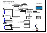
Page 24: ...rt Stereo in Scart RGB in RGB_OUT Video Switch Sheet 04 VGA_YUV_SW Sync Switch Sheet 06 AVSYNC AHSYNC R G B PC_HS PC_VS TV_HS TV_VS RAIN GAIN BAIN PC_IN H6W LCDTV Production Reference Design Block Diagram PW1306 OR PW1308 WITH DVI PQFP208 Single Dual Pixel TTL Audio out Stereo out Scart Stereo out WXGA LCD TVs VGA_TV_SW 2X4W SE Rev Nov27 Scart CVBS in PC_AUDIO IN TMDS DVI_IN Scart2 CVBSO2 Scart CV...

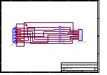
Page 25: ...Number Rev Date Sheet of FB709 100 0603 FB705 100 0603 CN702 HDR1X10 2mm Header 1 2 3 4 5 6 7 8 9 10 VCC P_T P_R U_D U_C GND V3 3D FCEn ICEn RESETN FB701 100 0603 FB706 100 0603 FB702 100 0603 FB707 100 0603 FB703 100 0603 CN701 DB15HD 1 2 3 4 5 6 7 8 9 10 11 12 13 14 15 16 17 FB708 100 0603 FB704 100 0603 ...

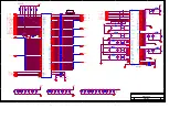
Page 26: ... V656_2 V656_3 V656_4 V656_5 V656_6 V656_7 VPEN VCLK NMI XI XO A1 A2 A3 A4 A5 A6 A7 A8 A9 A10 A11 A12 A13 A14 A15 A16 A17 A18 A19 D0 D1 D2 D3 D4 D5 D6 D7 D8 D9 D10 D11 D12 D13 D14 D15 RD WR ROMOE ROMWE CS0 CS1 C46 0 01uF C28 18pF RN11 47 1 3 4 5 6 7 8 2 C10 0 1uF FB6 10 0805 FB81 10 0805 R13 100 C23 0 1uF RN13 47 1 3 4 5 6 7 8 2 C47 0 1uF R14 100 C22 0 1uF R8 3 3K RN14 47 1 3 4 5 6 7 8 2 C15 1000p...

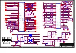
Page 27: ...GREF_SDAC1 VREF_SDAC2 GREF_SDAC2 VREF_SDAC3 DECDIG V8SWTCH FB17 10 0805 R70 NC R65 NC C54 0 22uF R68 NC R30 47K C122 1000pF R32 1K C68 0 1uF C61 0 1uF R103 NC C120 6 8nF R34 47K FB12 10 0805 FB22 10 0805 C74 10V10uF C55 0 1uF C69 0 1uF C75 0 1uF R61 NC R44 12K C73 0 1uF C65 0 1uF FB13 10 0805 C96 0 1uF R24 1K C84 0 01uF C98 0 22uF R104 0 C105 0 1uF C125 10V100uF R49 2 2 R26 1K C108 0 22uF FB18 10 ...

Page 28: ...D U_C GND V3 3D FCEn ICEn RESETN CN2 HDR1X1 2 54mm Header 1 R6 4 7K C172 10V10uF CN6 HDR1X11 SMT RT2mm 1 2 3 4 5 6 7 8 9 10 11 R80 3 3K C350 0 1uF C140 0 1uF C136 0 1uF R76 10 C167 0 1uF GAIN1 R77 10 C173 0 1uF DCLK1 R22 NC R257 3 3K BAIN1 R7 4 7K U4 AM29LV800BT 90EC 37 13 46 27 29 30 31 32 33 34 35 36 38 39 40 41 42 43 44 45 1 2 3 4 5 6 7 8 17 18 19 20 21 22 23 24 25 48 26 28 11 12 14 47 16 VCC V...

Page 29: ... 100pF FB41 100 0603 R126 100 C143 10V10uF C193 100pF C201 100pF C207 100pF R132 100 R91 0 R143 100 C183 100pF R90 0 R139 47K R128 75 FB48 100 0603 C156 12pF C175 100pF C155 12pF FB32 100 0603 C205 10uF C154 12pF 2 3 4 1 CN8 CONN DIN4 4 3 2 1 C145 20pF C208 100pF C148 0 1uF C211 100pF C146 20pF FB39 100 0603 FB47 100 0603 R144 75 R99 75 R127 100 FB43 100 0603 R88 1K2 R112 1K R100 75 C178 22nF D5 B...

Page 30: ...9 100K R168 0 Q12 MMBT3904L 3 1 2 U10 EL1883 SO 8 6 8 4 2 3 7 1 IO VCC GND VIN VS HS SYNC C223 33pF R154 10K C214 10uF 1 2 U11B 74HC123_0 6 7 9 10 11 5 12 16 8 CEXT REXT CEXT A B CLR Q Q VCC GND C228 1uF R166 270K R162 27 Q14 MMBT3904L 3 1 2 R161 75 R146 0_NS C219 10V10uF C213 0 1uF R171 10K R149 75 Q13 MMBT3904L 3 1 2 R155 10K R35 12K R169 100 R167 0 C222 33pF R165 4K7 R150 27 CN12 DVI_AD_CON 1 2...

Page 31: ...ML C235 NC C253 0 1uF R190 NC U16 74HC4052D 9 4 12 6 15 14 11 1 5 3 2 10 13 16 8 7 B Y3 X0 INH X2 X1 X3 Y0 Y1 Y Y2 A X VCC GND VEE R197 NC C244 0 22uF R211 75 R193 NC U13 NC 6 8 9 19 17 16 1 14 11 20 3 4 5 15 7 10 18 23 24 2 YIN UIN VIN YOU UOUT VOUT SC SDA SCL VCC ADCEXT1 ADCEXT2 ADCEXT3 DECDIG ADR TP VEE NC NC NC C245 0 1uF R216 75 D32 1N4148 1 2 C190 10V2 2uF Q19 NC 1 2 3 C258 10V47uF FB55 10 0...

Page 32: ... 28 29 30 31 32 33 34 35 36 37 38 39 40 41 42 43 44 45 46 47 48 49 50 Q26 NC 3 1 2 C279 0 1uF R238 2K C273 10V10uF C275 0 01uF R256 NC C276 0 01uF Q27 MMBT3904L 3 1 2 R240 NC C277 0 01uF C274 10V10uF R239 0 R260 0 R241 470 R237 NC FB85 10 0805 CN17 1 2 3 4 5 6 7 8 9 10 11 12 13 14 15 16 17 18 19 20 21 22 23 24 25 26 27 28 29 30 31 32 33 35 37 39 34 36 38 40 41 FB62 10 1206 C272 0 01uF FB77 NC C177...

Page 33: ...0 1uF C303 10V10uF CN25 HDR1X4 3 96mm Header 1 2 3 4 1 2 3 4 C310 0 1uF C292 25V100uF C288 0 1uF D28 5820 R251 10K J32 1 2 C337 0 1uF C289 10V100uF FB71 10 1206 C287 10V10uF C181 10V2 2uF C325 0 01uF C311 0 1uF C299 0 1uF C317 0 1uF C285 0 1uF R249 3 3K C295 6 3V220uF C308 0 1uF C290 0 1uF C321 NC C318 10V100uF C336 0 1uF C341 10V100uF U30 LM1117 1 8V 1 2 3 4 GND OUT VIN 4 C333 0 1uF F1 5A FUSE C3...

Page 34: ...C408 0 1uF R404 22K C412 0 1uF R408 100 L408 47uH C406 10nF C414 0 1uF L402 10uH C409 0 1uF C413 50V270pF L407 47uH C404 47uF 16V C415 1uF CN401 HDR1X11 RT2mm 1 2 3 4 5 6 7 8 9 10 11 R403 47K C419 0 1uF R401 0 C416 1uF C418 0 1uF Q401 BC846B 3 1 2 C410 50V4 7nF C403 16V10uF C405 0 1uF C402 0 1uF L405 102K 0603 C401 0 1uF L406 102K 0603 C411 50V270pF C407 16V10uF C417 0 1uF R412 NC D30 BAV99L 1 3 2...

Page 35: ...PUSHBUTTON S502 PUSHBUTTON CN501 HDR1X11 SMT RT2mm 1 2 3 4 5 6 7 8 9 10 11 C509 0 01uF CN503 HDR1X4 2 54mm 1 2 3 4 L GND GND R C504 0 1uF S501 PUSHBUTTON C506 0 01uF C510 0 01uF CN506 HDR1X2 2 54mm 1 2 L GND C505 0 1uF S505 PUSHBUTTON CN507 HDR1X2 2 54mm 1 2 R GND C511 0 01uF J508 PHONEJACK STEREO 1 2 3 4 5 6 7 8 9 R502 470 C507 0 01uF S503 PUSHBUTTON CN502 4PIN2 0MM 1 2 3 4 S507 SW PUSHBUTTON 1 2...

Page 36: ...D REMOTE VCC5 IR BOARD B A H6L LCD TV 12 14 Wednesday October 13 2004 Title Size Document Number Rev Date Sheet of D511 R513 10K CN511 4PIN2 0MM 1 2 3 4 U511 IR 3 2 1 DAT VCC GND R514 4 7K R512 75 R511 100 Q511 A1815 C512 47uF 10V R515 4 7K C513 0 1uF ...

Page 37: ...r 13 2004 Title Size Document Number Rev Date Sheet of C625 10uF R625 1K R624 100K FB621 11_OHM 100MHz R622 330 C621 100pF CN622 HDR1X5 RT2 54mm 1 2 3 4 5 C622 100pF R626 1K C626 10uF R621 330 C623 100pF Yellow White Red CN621 3RCA_AV_OUT 6 1 5 3 4 2 R623 100K C624 100pF FB622 11_OHM 100MHz ...

Page 38: ...2004 Title Size Document Number Rev Date Sheet of 12V 24V U631 LM2679S 12 2 5 6 4 1 8 3 7 VIN ILIM FBK GND OUT TAB CB SS C632 50V100uF D631 MBR745 L631 33uH 5A R631 4 7K C641 0 1uF C636 0 01uF C637 16V330uF C635 0 1uF CN631 HDR1X4 RT3 96mm 1 2 3 4 C634 0 47uF C633 50V100uF C638 16V330uF C639 16V330uF C640 16V330uF ...

Page 39: ...39 ...

Reviews: