background image

3

FOR YOUR PERSONAL SAFETY

1.

When the power cord or plug is damaged or frayed, unplug this television set from the wall outlet and refer servicing to
qualified service personnel.

2.

Do not overload wall outlets and extension cords as this can result in fire or electric shock.

3.

Do not allow anything to rest on or roll over the power cord, and do not place the TV where power cord is subject to
traffic or abuse. This may result in a shock or fire hazard.

4.

Do not attempt to service this television set yourself as opening or removing covers may expose you to dangerous
voltage or other hazards. Refer all servicing to qualified service personnel.

5.

Never push objects of any kind into this television set through cabinet slots as they may touch dangerous voltage
points or short out parts that could result in a fire or electric shock. Never spill liquid of any kind on the television set.

6.

If the television set has been dropped or the cabinet has been damaged, unplug this television set from the wall outlet
and refer servicing to qualified service personnel.

7.

If liquid has been spilled into the television set, unplug this television set from the wall outlet and refer servicing to
qualified service personnel.

8.

Do not subject your television set to impact of any kind. Be particularly careful not to damage the picture tube surface.

9.

Unplug this television set from the wall outlet before cleaning. Do not use liquid cleaners or aerosol cleaners. Use a
damp cloth for cleaning.

10.1. Do not place this television set on an unstable cart, stand, or table. The television set may fall, causing serious injury

to a child or an adult, and serious damage to the appliance. Use only with a cart or stand recommended by the
manufacturer, or sold with the television set. Wall or shelf mounting should follow the manufacturer s instructions, and
should use a mounting kit approved by the manufacturer.

10.2. An appliance and cart combination should be moved with care. Quick stops, excessive force, and uneven surfaces

may cause the appliance and cart combination to overturn.

CAUTION:

Read all of these instructions. Save these instructions for later use. Follow all Warnings and
Instructions marked on the audio equipment.

1. Read Instructions- All the safety and operating instructions should be read before the product is operated.

2. Retain Instructions- The safety and operating instructions should be retained for future reference.

3. Heed Warnings- All warnings on the product and in the operating instructions should be adhered to.

4. Follow Instructions- All operating and use instructions should be followed.

IMPORTANT SAFETY INSTRUCTIONS

Summary of Contents for M28SPG8

Page 1: ...s 6 3 Alignment Procedure 7 4 BLOCK Diagram 26 5 Schematic Diagram 27 6 PCB Layout 28 7 Explode View 30 8 BOM list 31 This manual is the latest at the time of printing and does not include the modific...

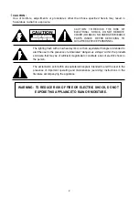
Page 2: ...er to the presence of uninsulated voltage within the products enclosure that may be of sufficient magnitude to constitute a risk of electric shock to the person The exclamation point within an equilat...

Page 3: ...nnel 8 Do not subject your television set to impact of any kind Be particularly careful not to damage the picture tube surface 9 Unplug this television set from the wall outlet before cleaning Do not...

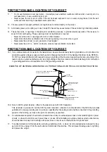
Page 4: ...porting structure grounding of the lead in wire to an antenna discharge unit size of grounding conductors location of antenna discharge unit connection to grounding electrode and requirements for the...

Page 5: ...21 If you are unable to restorenormal operation by following the detailedprocedurein your operating instructions do not attempt any further adjustment Unplug the set and call your dealer or service te...

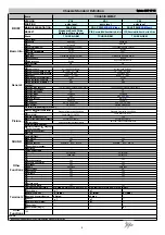
Page 6: ...ose Caption V chip AV Stereo Yes NICAM No Sound control VOLUME AVC MUTE Super woofer speaker Surround Clock Timer function on off timer Lock Child Lock Curtain Blue background Yes Favorite channel lis...

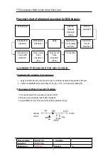
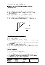
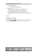
Page 7: ...h adjustment Screen center size adjustment PAL Screen center size adjustment NTSC QC checking ALIGNMENT PROCEDURE FOR M28 CHASSIS I Adjustment of B voltage for VR840 model only 1 Apply 180V 240VAC r5V...

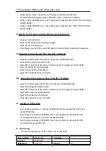
Page 8: ...and d to the same IV Adjustment of Focus Screen Voltage and Sub brightness 1 Receive a crosshatch pattern 2 Adjust the FOCUS VR on the flyback the make the picture clear 3 Enter D mode and press MUTE...

Page 9: ...tal center 3 Select VP50 to adjust the Vertical center If Vertical output is DC Coupling pls adjust VCENP 4 Select HIT to adjust the Vertical amplitude 5 Select VLIN to adjust the vertical linearity 6...

Page 10: ...t ninth fonts are available in the first line Press OK in twice for save and exit at the same time NOTEBOOK off Choose OEMC Press key FM in D Mode item to set the color of customer logo font Choose OE...

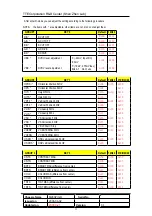
Page 11: ...OUP2 KEY 1 Default 14N23 21E N23 26 HPOS Horizontal Position 50HZ HPS Horizontal Position 60HZ HIT Height 50Hz HITS Height 60 Hz VP50 Vertical Position 50Hz VP60 Vertical Position 60HZ VLIN V Linearit...

Page 12: ...0x1B 0x1B 0x14 SV4 SHARP CENTER OTHER VIDEO 0x20 0x20 0x18 SVD SHARP CENTER DVD 0x18 0x18 0x18 ASSH ASYMMETRY SHARPNESS 0x05 0x05 0x00 SHPX SHARP MAX difference from center 0x07 0x07 0x07 SHPN SHARP M...

Page 13: ...PRESET 1 AUTO STBY 0 1 2 3 hd kill timer set 40us 4 when STBY 5 0 after AC on 0 standby 1 power on 5 after AC power on 0 ref STBY 4 1 last state 6 Biological Clock 0 disable 1 enable 7 Child Lock 1 d...

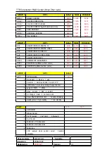
Page 14: ...able MUTT standby wake time 0x00 STAT contrast up timer after standby off 0x00 GROUP 7 KEY 7 RFAGC RF AGC SBY SECAM B Y BLACK ADJUST SRY SECAM R Y BLACK ADJUST BRTS SUB BRIGHT shift data of BRTC TXCX...

Page 15: ...ng 7 KILLER OFF 6 P N ID 5 C GAMMA 4 3 NTSC MATRIX 2 1 0 Y DL ABL 0x27 7 Auto Sleep 0 Waking up State 1 Enter Auto sleep State 6 OSD ABL Mode 0 ABL is effective to OSD 1 Ineffective 5 Don t use 4 Y Pe...

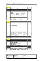
Page 16: ...TV hafc gain depend on noise 0 1 2 in video mode hafc gain 3 NOIS HAFC DATA 0 noise det 1 2 fix the hafc gain UCOM MCU DATA New Factory Adjustable Items Descriptions for M28L G2 Solution V1 0 Group KE...

Page 17: ...mode 00 2 10 Vp p 01 2 20 Vp p 10 2 30 Vp p 4 5 PIF Detected Level 11 2 40 Vp p 00 ALC off 01 1 1 Vp p 10 1 6 Vp p VCD1 6 7 ALC Gain 11 2 3 Vp p 0x41 Group KEY SCAN Items Bit Description Default 0 Of...

Page 18: ...1 2 5 V then active 5 X Ray protection mode 0 2 5V then active 1 Internal ATT 6 Volume adjustment mode 0 External Power AmplifierAtt 0 Off MODE2 7 Hi Senstive 1 On 0x82 0x09 0 Normal 0 Sync slice lev...

Page 19: ...arch and Tuning 00 H Lock 01 Don t use 02 V Lock 2 5 Select the input IF signal level of sync lock detection bit 5 4 3 2 1 0 0 0 8dB weak signal 1 0 1 0 4dB 1 0 11 0 0 0dB Others Don t use SYSR 6 7 Do...

Page 20: ...2 10 Q 7 3 Sound Trap Q for BG 11 Q 9 00 Off 01 1 dB HPF 4 10 3 dB LPF 5 Sound Trap HP LP for BG 11 2 dB LPF SSBG 6 7 Don t use 0x00 00 Off 01 60nS 0 10 90nS 1 Sound Trap GD for I 11 120nS 00 Q 3 01 Q...

Page 21: ...Trap Q for M 11 Q 9 00 Off 01 1 dB HPF 4 10 3 dB LPF 5 Sound Trap HP LP for M 11 2 dB LPF SSM 6 7 Don t use 0x00 Group Key FM Items Bit Description Default 0 NDTC 0 7 Counter for non weak signal detec...

Page 22: ...value for RCUT of Warm 0 7F 1 subtract operation WRCUT 7 Sign bit 0 add operation 0x00 0 6 Available offset value for GCUT of Warm 0 7F 1 subtract operation WGCUT 7 Sign bit 0 add operation 0x03 0 6...

Page 23: ...r BDRV of Cool 0 7F 1 subtract operation CBDRV 7 Sign bit 0 add operation 0x0B Items Bits Description Default 0 6 RCUT offset for white balance in YUV mode 0 Min 8 0 mv F Max 1 subtraction UVRCUT 7 Si...

Page 24: ...normal 01 200ns delay 10 Center 11 200ns forward 2 S Inhibit 0 Detecting 1 SECAM inhibit 3 S ID Select SECAM ident sensitivity 0 Normal 1 Low 4 Bell SW Select SECAM bell filter bandwidth 0 Bell filter...

Page 25: ...M28SP G8 Serial No Issued on 2006 06 02 Updated on 2007 3 21 Version 3 1 KLWH DODQFH 5 5 03 03 03 5 87 87 87 2IIVHW 7 ZULWH V 6XE GG 6WDUW LW 6W S LW 3520 6XE GG V 5HIHUHQFH R Based on Socket order 9...

Page 26: ...101 IF AMP Q101 SAW Z101 TMPA8873 IC201 2 Q501 Q503 Q505 AMP R G B CRT R G B V AMP IC301 V out H drive AMP Q401 Q402 H out FBT T402 220V 24V 6 3V EHT FOCUS SCREEN TMPA8873 IC201 1 E 2 PROM IC002 KEY I...

Page 27: ......

Page 28: ......

Page 29: ......

Page 30: ......

Page 31: ...NX RES C F 4 3K OHM 1 6W 5 1 PC R025A 18 CB0470 JNX RES C F 47 OHM 1 6W 5 1 PC R013A 18 CB0622 JNX RES C F 6 2K OHM 1 6W 5 1 PC R026A 40 21T28H FBC1XG P C B FRONT CABINET 1 PC 41 WJ0065 B00 1 R N 1 PC...

Page 32: ...KBS CAP CER 1000 PF 50V 20 1 PC C901 41 WJ0060 B00 WIRE BARE 1 PC J910 41 WJ0065 B00 1 R N 1 PC C902 41 WJ0075 B00 WIREBAREJUMPER7 5MM 1 PC J015 41 WJ0090 B00 WIREBAREJUMPER9MM 1 PC J906 10 0FR104 FBX...

Page 33: ...2 JNX RES C F 1K OHM 1 6W 5 1 PC R616 18 CB0102 JNX RES C F 1K OHM 1 6W 5 1 PC R107 18 CB0102 JNX RES C F 1K OHM 1 6W 5 1 PC R013 18 CB0102 JNX RES C F 1K OHM 1 6W 5 1 PC R616B 18 CB0102 JNX RES C F 1...

Page 34: ...PC R406A 18 CB0332 JNX RES C F 3 3K OHM 1 6W 5 1 PC R208 18 CB0332 JNX RES C F 3 3K OHM 1 6W 5 1 PC R218A 18 CB0332 JNX RES C F 3 3K OHM 1 6W 5 1 PC R255 18 CB0391 JNX RES C F 390 OHM 1 6W 5 1 PC R21...

Page 35: ...EC 470 UF 16V 20 1 PC C601 25 BCB471 M1X CAP ELEC 470 UF 16V 20 1 PC C602 25 BCB471 M1X CAP ELEC 470 UF 16V 20 1 PC C602B 25 BDB470 M1X CAP ELEC 47 UF 25V 20 1 PC C032 25 BEB101 M1X CAP ELEC 100 UF 35...

Page 36: ...3 ZFS CAP CER 10NF 50V 80 20 1 PC C239 26 EBP103 ZFS CAP CER 10NF 50V 80 20 1 PC C114 26 EBP103 ZFS CAP CER 10NF 50V 80 20 1 PC C005 26 EBP103 ZFS CAP CER 10NF 50V 80 20 1 PC C233 26 EBP103 ZFS CAP CE...

Page 37: ...ARE 1 PC J918 41 WJ0060 B00 WIRE BARE 1 PC J903 41 WJ0060 B00 WIRE BARE 1 PC R416 41 WJ0060 B00 WIRE BARE 1 PC R228A 41 WJ0060 B00 WIRE BARE 1 PC R618 41 WJ0060 B00 WIRE BARE 1 PC J005 41 WJ0060 B00 W...

Page 38: ...MPER11 5MM 1 PC J607 41 WJ0120 B00 WIREBAREJUMPER12MM 1 PC J603 41 WJ0120 B00 WIREBAREJUMPER12MM 1 PC J605 41 WJ0125 B00 WIREBAREJUMPER12 5MM 1 PC J402 41 WJ0125 B00 WIREBAREJUMPER12 5MM 1 PC J902 41...

Page 39: ...9K OHM 1 4W 5 1 PC R808 18 CD0472 JNX RES C F 4 7K OHM 1 4W 5 1 PC R812 18 CE0224 JNX RES C F 220K OHM 1 2W 5 1 PC R803A 18 CE0224 JNX RES C F 220K OHM 1 2W 5 1 PC R803 18 KE0105 JNX RES GLASS GLAZE...

Page 40: ...0 33 UF 250V 1 PC C421 27 ALR123 J0X CAP M PP 0 012 UF 1 6KV 5 1 PC C406 36 LIN500 XX1 COIL LINEARITY 50 UH 1 PC L412 37 FBAT04 CAA0A FBT BSC25 0252T 1 PC T402 18 FG0153 JHX RES M O 15K OHM 2W 5 1 PC...

Page 41: ...6 UH 10 1 PC L402 36 HDR020 XX0 TRANSFORMER HORIZ DRIVE BCT 1621 1 PC T401 45 OSC8M0 0Y0B CRYSTAL 8 0MHZ CCL 30PF 1 PC X001 46 39402W 04XG BASE 1 PC P401 62 227680 0UA TV RAW SUPPORT CABLE CHASSIS 1...

Page 42: ...0 35 139730 00X FERR BEAD BF60 1 PC L810 FOR D832 35 139730 00X FERR BEAD BF60 1 PC L811 FOR D832 35 139730 00X FERR BEAD BF60 2 PC FOR R815 35 139730 00X FERR BEAD BF60 1 PC L806 FOR D831 36 LIF004 A...

Reviews: