background image

No. SEB-81BBE

TCM CORPORATION

FORKLIFT TRUCK

FB10

-7

FB15

-7

FB18

-7

FB20

-7

FB25

-7

FB30

-7

FB25

-7LB

FB25

-7V

FB30

-7V

FB35

-7S

Counter Balanced

Summary of Contents for FB10-7

Page 1: ...No SEB 81BBE TCM CORPORATION FORKLIFT TRUCK FB10 7 FB15 7 FB18 7 FB20 7 FB25 7 FB30 7 FB25 7LB FB25 7V FB30 7V FB35 7S Counter Balanced...

Page 2: ......

Page 3: ...ve motors are used the first class acceleration gradeability and traveling performance are achieved Controllability is also improved by the standard equipped power steering unit To save power the acce...

Page 4: ...No SEB 81BBE...

Page 5: ...Min intersecting aisle mm in 1690 66 5 1730 68 1 Dimensions Overall length includ fork C mm in 2875 113 2 2975 117 1 Overall width D mm in 1070 42 1 Overall height Overhead guard E mm in 2050 80 7 Ov...

Page 6: ...6 1905 75 0 1955 76 9 Dimensions Overall length includ fork C mm in 3315 130 5 3355 132 3460 136 Overall width D mm in 1150 45 3 Overall height Overhead guard E mm in 2095 82 5 LB 2250 88 6 V 2100 82...

Page 7: ...imensions Overall length includ fork C mm in 3580 141 3835 151 0 Overall width D mm in 1225 48 2 1380 54 3 Overall height Overhead guard E mm in 2190 86 2 V 2100 82 7 Overall extended height mm in 426...

Page 8: ...No SEB 81BBE...

Page 9: ...No SEB 81BBE Fig 1 Overall Dimensions Unit mm in...

Page 10: ...No SEB 81BBE...

Page 11: ...1 INVERTER 29 3 1 2 ACCELERATOR PEDAL 34 3 1 3 INTERLOCK SYSTEM 35 3 1 4 BACK DOWN ALARM SYSTEM 36 3 2 MAINTENANCE 37 3 2 1 TROUBLESHOOTING GUIDE 37 4 DRIVE UNIT AND DRIVE AXLE 55 4 1 GENERAL DESCRIPT...

Page 12: ...2 CONTROL VALVE 104 7 1 3 HYDRAULIC OIL TANK 108 7 1 4 LIFT CYLINDER 109 7 1 5 FLOW REGULATOR VALVE 114 7 1 6 TILT CYLINDER 116 7 2 MAINTENANCE 118 7 2 1 MAINTENANCE OF PUMP 118 7 2 2 TRIAL RUN 130 7...

Page 13: ...arger Type Truck mounted type 3 phase AC semiconstant voltage charger Rated power 6 0 kVA 8 5 kVA Rated current 17 A 24 A Power supply voltage 380 440 V Applicable battery capacity 320 500 AH 5h 450 7...

Page 14: ...f discharge can be known by measuring the specific gravity of the electrolyte See Fig 1 3 Check the level of electrolyte every ten days Add distilled water if the level is found lower than the specifi...

Page 15: ...e battery and its service life will be shortened For a truck mounted type charger a microcomputer determines when an equalizing charge is required and carries out equalizing charge automatically Cauti...

Page 16: ...ry wire Contactor VTM unit Primary wire Thermal relay secondary wire contactor VTM unit primary wire thermal relay Connection of primary wire portion not used Connection of secondary wire Thermal rela...

Page 17: ...ging The supply voltage varies with the periods of time Change therefore the taps from one to another according to the average of supply voltages which to charger receives for the period of time durin...

Page 18: ...eed controller is a 3 phase full wave rectification type which converts AC to DC The current rectified by the diode flows through the fuse F6 to charge the battery FUSE 130A FB25 7LB FB25 7V 200A CHAR...

Page 19: ...timal charge This setting voltage is compensated properly to provide optimal charge even if there are temperature changes Super equalizing charge The microprocessor counts the charging time and automa...

Page 20: ...erature and voltage settings of charge sessions performed within the last 40 hours 94 hours for trucks manufactured earlier than January 31 2004 The total charging hours and the total hours during whi...

Page 21: ...AND CHARGER 9 COMMUNICATION LED ROTARY SWITCH 4 DIGIT LED SWITCHES MODE HIGH LOW SETTING MODE SYMBOL ROTARY SWITCH CALLING UP 4 DIGIT LED Fig 1 9 VTM Unit for trucks manufactured on and after Februar...

Page 22: ...of the said truck Note 2 Do not change the other settings on the VTM unit Mode Factory set level Change Traveling and lifting speeds They are increased by increasing the level Traveling speed change N...

Page 23: ...ng changes to and to every time the mode setting switch SW2 is pressed The 1st digit shows the mode symbol and the 2nd digit the speed limit or operating level number Set the 1st digit to the mode sym...

Page 24: ...rotary switch number 2nd digit the mode and the last two digits the speed limit or operating level Every time the mode switch is pressed the mode will change from P S and to Set the mode switch to th...

Page 25: ...r supply at the facility side Remove the plug at the truck side with its lock lever pressed After charging is finished measure the specified gravity of the battery electrolyte to check if the proper c...

Page 26: ...attery service life will be short It is recommended to adopt a high capacity battery or to prepare a spare battery when super equalizing charge is so often used 5 Flickering CHARGING lamp When chargin...

Page 27: ...connected to the transformer by the action of the magnet switch CM LED1 lights up the fail timer starts counting down the time and charging operation starts The fail timer is set to 15 hours for norm...

Page 28: ...1 BATTERY AND CHARGER 16 NOTE...

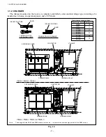
Page 29: ...or Rated output 8 6 kW 5 min rate 9 kW 5 min rate 14 kW 5 min rate Rated voltage 48 V 48 V 68 V Rated current 260 A 265 A 262 A Weight 38 kg 83 8 lbf 45 kg 99 2 lbf 61 kg 134 5lbf 2 1 GENERAL DESCRIPT...

Page 30: ...2 MOTORS 18 DRIVE UNIT Fig 2 1 Drive Motor Installation DRIVE AXLE DRIVE MOTOR...

Page 31: ...SC THERMO SENSOR CONNECTOR FRONT BRACKET SPEED SENSOR B SPEED SENSOR A W PHASE V PHASE U PHASE SLITTED DISC Two slitted discs are joined by aligning their respective teeth WAVE WASHER SNAP RING Detail...

Page 32: ...in Y or delta connection The sketch b in Fig 2 4 shows a typical Y connection which is widely used for the connection of induction motors When the directions A A B B C C in which current flows into th...

Page 33: ...main pump Its rotation is controlled by the load handling chopper built in the speed controller only when the lift lever is operated Except that the pump motor is used for starting or stopping the ro...

Page 34: ...2 MOTORS 22 Fig 2 7 Pump Motor BRUSH WEAR INDICATOR THERMAL SWITCH BRUSH COVER BRUSH HOLDER BRUSH CLAMP FIELD COIL YOKE AMATURE FAN...

Page 35: ...exceeded stop the motor and remove the cause If any defect is found stop the motor and remove the cause Check item Dust Foreign matter splash liquid Temperature rise Vibration Noise Location Motor fra...

Page 36: ...rease leaks noise adherence of dust visually or audibly Check for damage or rough surface due to corrosion visually Check for looseness corrosion or seizure visually or by tapping Check for damage or...

Page 37: ...ng otherwise the insulation will be impaired Use a dry cloth or soft brush for cleaning If the insulation resistance of the coil is lower than the specified value dry the coil by heating it to 80 90 C...

Page 38: ...ng the following table as a rough guide Operation time 8 12 hours day 12 hours day Replacement intervals Once every 6 years Once every 3 years Earlier replacement may be required if the motor is used...

Page 39: ...o the motor yoke and the positive terminal to either one of the two lead wires Then measure the resistance It is normal when the pointer of the meter indicates higher than 1 M If the meter reads than...

Page 40: ...ing If it is cut the depth of the segment mica should also be corrected Finish the depth of the mica to 0 8 to 1 0 mm 0 0315 0 0394 in measured from the surface of the commutator for both the pump mot...

Page 41: ...is shown in Fig 3 1 The inverter consists primarily of a CPU board a power supply board and an FET module Its schematic diagram is shown in Fig 3 2 The CPU board receives signals from the accelerator...

Page 42: ...3 CONTROL SYSTEM 30 Fig 3 2 Inverter Assembly 1 0 to 2 5 ton Trucks...

Page 43: ...31 3 CONTROL SYSTEM Fig 3 3 Inverter Assembly 3 0 to 3 5 ton Trucks...

Page 44: ...3 CONTROL SYSTEM 32 Fig 3 4 Controller Wiring 1 0 to 2 5 ton Trucks...

Page 45: ...33 3 CONTROL SYSTEM Fig 3 5 Controller Wiring 3 0 to 3 5 ton Trucks...

Page 46: ...o the controller 1 Apply a voltage of 5 0 01 V between 95 and 41 2 Turn potentiometer clockwise in neutral state and lock it at a position at which the voltage between 93 and 41 shows 0 1 V 0 1 V 3 Mo...

Page 47: ...lever in neutral Do not leave the operator s seat while the forks are lowering otherwise the forks stop lowering abruptly causing the load to fall off the forks Do not leave the operator s seat while...

Page 48: ...ling levers into neutral to release the interlock 3 seconds passed The operator leaves the operator s seat when the key switch is in the ON position How to release Turn the key switch to OFF sit down...

Page 49: ...F or R or accelerator pedal operation Truck comes to stop during traveling Hard steering wheel Error Harness disconnected between power supply board and CPU board DSW1 improperly set Reverse connectio...

Page 50: ...epair or change if needed Check traveling power modules TMDU TMDV TMDW and repair or change if needed When changing any defective power module change power supply board too Check harness between CN3R...

Page 51: ...P1 terminal and repair or change if needed Check thermo sensor THD voltage and change if needed Check harness between CN7 5 11 CPU board and thermo sensor THD and repair or change if needed Operate th...

Page 52: ...tage of traveling motor thermo sensor and change if needed Check harness between CN11 3 4 CPU board and traveling motor thermo sensor and repair or change if needed Check harness between CN2 3 4 CPU b...

Page 53: ...N terminals for looseness and retighten if needed Check traveling contactor see error code 04 Check load handling contactor see error code 33 Check contactor drive Tr see error codes 07 and 38 Check t...

Page 54: ...and repair or change if needed Check load handling motor and wiring and repair ore change if needed If no defect is found throughout the above steps change the power supply board too Check load handli...

Page 55: ...Change CPU board drive Tr defective Cool down the controller Check TMP for loose fitting screws Check the resistance voltage of thermo sensor THP and change if needed Check harness between CN7 6 12 CP...

Page 56: ...ess between CN4 1 CPU board and P22 terminal and repair or change if needed Check PS main fuse F3 and change if needed Check harness between CN4 9 CPU board and P21 terminal and repair or change if ne...

Page 57: ...ance digital tester cannot be used for this purpose 7 Oscilloscope Check transistor circuit 8 Stabilized power 0 50 V variable 3A conductable Check operation of each component supply for control Where...

Page 58: ...ape of heat dissipation insulation sheet when fitted to the machine Symbol Position Truck model 1 ton model 2 and 3 ton model TMP upper side Short and narrow Short and narrow lower side Short and wide...

Page 59: ...the case cover first remove the wire harness connector from the board remove the screws 9 for securing the CPU board 9 for securing power supply board and then detach the board from the base When rem...

Page 60: ...es shown above should be used as a rough guide The Normal value varies with different types of tester and the internal battery s state of charge When checking the gates G1 G2 you can check the gate de...

Page 61: ...ing insulation sheet is placed between the FET power module and aluminum fin to provide electrical insulation while transmitting generated heat to the aluminum fin efficiently When replacing the FET p...

Page 62: ...terminal of the F1 fuse and then to the lower terminal to measure the voltage at each terminal Voltage table key switch turned ON Location Voltage value Judgment Lower terminal Battery voltage Good 0...

Page 63: ...roller Attach the positive pole of the tester to each of the pins 3 4 5 6 14 15 16 and 17 of the CN5 22 pin connector and turn on the key switch to measure the voltage Voltage table key switch turned...

Page 64: ...f it functions smoothly Push further after contacts are closed to check if the compression spring is properly compressed to press the contacts If any defect is found throughout the above steps replace...

Page 65: ...multiple aluminum electrolytic capacitors connected in parallel and installed just above the FET power module These capacitor boards absorb a surge voltage generated from the FET power module to preve...

Page 66: ...ceeds a certain level the output current is restricted Remove the motor thermo sensor connector Set the tester to a resistance range of x 1000 and measure the resistance between terminals using the te...

Page 67: ...GENERAL DESCRIPTION 4 1 1 DRIVE UNIT The drive unit is a three stage reduction type and located between the drive motor and the drive axle as shown in Figs 4 1 through 4 3 The drive gear is splined t...

Page 68: ...n O RING O RING MOTOR STOPPER COUNTER GEAR O RING COUNTER GEAR Tightening torque 44 to 54 N m 450 to 550 kgf cm 389 4 to 477 9 lbf in Tightening torque 278 to 416 N m 2800 to 4200 kgf cm 2460 5 to 368...

Page 69: ...STOPPER COUNTER GEAR O RING COUNTER GEAR Tightening torque 44 to 54 N m 450 to 550 kgf cm 389 4 to 477 9 lbf in Tightening torque 278 to 416 N m 2800 to 4200 kgf cm 2460 5 to 3681 9 lbf in Apply LOCTI...

Page 70: ...PER COUNTER GEAR O RING COUNTER GEAR Tightening torque 278 to 416 N m 2800 to 4200 kgf cm 2460 5 to 3681 9 lbf in Apply LOCTITE 262 Tightening torque 95 to 142 N m 970 to 1450 kgf cm 840 8 to 1257 lbf...

Page 71: ...iven by the axle shaft Fig 4 4 Drive Axle 1 to 1 8 ton Trucks TAPERED ROLLER BEARING OIL SEAL ADJUSTMENT NUT LOCK NUT Tightening torque 98 to 113 N m 1000 to 1150 kgf cm 870 to 1000 lbf in Apply LOCTI...

Page 72: ...DRUM WHEEL BRAKE OIL SEAL TAPERED ROLLER BEARING OIL SEAL HUB ADJUSTMENT NUT LOCK NUT Tightening torque 206 to 225 N m 2100 to 2290 kgf cm 1820 to 1990 lbf in Apply LOCTITE 270 Tightening torque 140 t...

Page 73: ...kgf cm 4170 to 4860 lbf in BRAKE DRUM WHEEL BRAKE OIL SEAL TAPERED ROLLER BEARING OIL SEAL HUB ADJUSTMENT NUT LOCK NUT Tightening torque 471 to 549 N m 4800 to 5600 kgf cm 4170 to 4860 lbf in Fill 50...

Page 74: ...bf ft torque and loosen it by 1 2 turn 3 Set the spring balancer to the stud bolt Adjust the starting torque of the hub while tightening the adjustment nut gradually Starting torque 4 9 to 6 9 N m 50...

Page 75: ...1 91 x 0 20 in 11 88 x 2 2 x 0 2 in 13 7 x 3 0 x 0 31 in Surface area 4 x 13530 mm2 4 x 33200 mm2 4 x 26400 mm2 4 x 30 in 2 4 x 51 5 in 2 4 x 40 9 in2 Parking brake Type Front two wheel braking intern...

Page 76: ...5 BRAKE SYSTEM 64 Fig 5 2 Brake Pedal BRAKE SWITCH RESERVE TANK MASTER CYLINDER BRAKE SWITCH OPERATION DISTANCE 5 10 mm 1 97 3 94 in Height 90 mm 35 43 in View looking from A...

Page 77: ...s installed on the piston slide inside the cylinder when brake pedal is operated The check valve is operated so that the proper pressure remains in the wheel cylinder and brake pipe This pressure keep...

Page 78: ...er and strut The lever is installed on the primary shoe side with a pin Movement of the lever is also transmitted to the secondary shoe side through the strut 5 1 3 WHEEL BRAKE The wheel brake is duo...

Page 79: ...shown in Fig 5 7 At this step the section B of the lever turns the adjuster As the braking force becomes stronger the more force is applied to the threaded area of the adjuster and the force of the l...

Page 80: ...e is released and the operator leaves the seat the alarm buzzer will keep sounding How to release the alarm Sit down or pull on the parking brake lever to set the brakes Adjusting brake switch Loosen...

Page 81: ...ETURN SPRING 6 STRUT 7 SPRING 8 SHOE HOLD DOWN PIN 9 PRIMARY SHOE 10 SPRING 11 ADJUSTER LEVER 12 ADJUSTER 13 SPRING 14 PUSH ROD 15 BOOT 16 CYLINDER 17 PISTON 18 SPRING 19 CUP Sectional view C C Sectio...

Page 82: ...ETURN SPRING 6 STRUT 7 SPRING 8 SHOE HOLD DOWN PIN 9 PRIMARY SHOE 10 SPRING 11 ADJUSTER LEVER 12 ADJUSTER 13 SPRING 14 PUSH ROD 15 BOOT 16 CYLINDER 17 PISTON 18 SPRING 19 CUP Shoe expanding direction...

Page 83: ...ake and the procedure for adjusting the brake pedal with the wheel brake and hub removed 5 2 1 DISASSEMBLING WHEEL BRAKE 1 Remove the shoe hold down pin adjuster lever adjuster and spring from the sec...

Page 84: ...securing the wheel cylinder Remove the wheel cylinder from the backing plate 6 Remove the E retainer which secures the parking brake cable to the backing plate After that remove the bolt securing the...

Page 85: ...lace any damaged or deformed one 3 Measure the free length of the wheel cylinder spring If the length is out of the standard value replace the spring 4 Measure the brake lining thickness and replace a...

Page 86: ...ue 117 7 to 137 3 N m 1200 to 1400 kgf cm 1042 to 1215 lbf in 4 Apply high temperature grease to the points shown in Fig 5 23 using caution to keep grease away from the lining a Shoe contacting surfac...

Page 87: ...the right screw is used for the right brake Install the adjuster so that its teeth do not make contact with the spring Install the return spring at the adjuster side with its longer hook attached to...

Page 88: ...eeth of the adjuster return with the lever they are adjusted properly after mounting the brake system on the truck 2 If the operation described above does not occur by pushing up the adjuster lever ta...

Page 89: ...ly tighten the push rod by its lock nut Adjusting brake switch 1 Make sure that the pedal upheight is the value shown in Fig 5 29 Loosen the brake switch lock nut 2 Remove the brake switch lead wire f...

Page 90: ...ystem 2 Maladjustment of brake shoe clearance 3 Overheating brake 4 Poor contact between brake drum and lining 5 Foreign matter sticking to lining 6 Foreign matter mixed in brake fluid 7 Maladjustment...

Page 91: ...roke 235 mm 9 3 in Controller Type Voltage controlling type Rated voltage 48 V 72 V Current limit Max 40 A Max 45 A Rear axle Type Elliot type Steering angle Inner wheel 85 8 83 5 Outer wheel 55 6 56...

Page 92: ...rection of the force The controller converts the signal from the potentiometer into the direction and amount of electric current which flows into the motor If an external force is applied to the steer...

Page 93: ...EARING 11 REAR COVER 12 O RING 13 GEARBOX 14 BALL NUT 15 NEEDLE BEARING 16 OIL SEAL 17 THRUST BEARING 18 SPRING 19 SENSOR HOUSING 20 O RING 21 THRUST BEARING 22 LOCK NUT 23 FRONT COVER 24 SLIDE RING 2...

Page 94: ...6 STEERING SYSTEM 82 Fig 6 3 Steering Linkage STEERING HANDWHEEL STEERING WHEEL LOCK LEVER JOINT STEERING GEARBOX DRAG LINK EPS ACTUATOR View looking from A...

Page 95: ...exes at the combination switch side with the front of the truck 3 Engage the vertexes of the combination switch with the concaves of the steering handwheel Fig 6 4 Steering Handwheel F R LEVER LIGHTIN...

Page 96: ...rods and knuckles The rear axle support with a bushing press fitted is attached to the support pins located at the front and rear of the axle The support is bolted to the rear frame The axle is so mo...

Page 97: ...ks NEEDLE BEARING OIL SEAL Sectional view A A KNUCKLE RIGHT TIE ROD RIGHT TIE ROD LEFT KNUCKLE LEFT CENTER ARM OIL SEAL NEEDLE BEARING THRUST BEARING KING PIN OIL SEAL TAPERED ROLLER BEARING ADJUSTMEN...

Page 98: ...Axle 2 to 3 5 ton Trucks KNUCKLE RIGHT TIE ROD RIGHT TIE ROD LEFT KNUCKLE LEFT CENTER ARM OIL SEAL NEEDLE BEARING THRUST BEARING KING PIN OIL SEAL TAPERED ROLLER BEARING ADJUSTMENT NUT COTTER PIN WASH...

Page 99: ...oss and the knuckle so that the knuckle rotates smoothly around the king pin with its load The upper and lower needle bearings and the thrust bearing are lubricated with grease through the grease fitt...

Page 100: ...1 kgf m 86 7 lbf in 4 Gently tapping the hub with a mallet make sure there is no looseness 5 Tighten the hub with a mallet give it a few turns Then measure the starting torque 6 Tapping the hub with a...

Page 101: ...he rim so that the head of the rim mounting bolt is located at the outside of the truck 3 Make sure that no one is at the tire side bead side while filling air into the tire 4 When the air pressure be...

Page 102: ...e Be sure to hold it in a lying position Fig 6 11 Fig 6 12 Fig 6 13 Fig 6 14 Remove the motor securing bolts then remove the motor Note Do not give a strong shock to the motor Remove the packing from...

Page 103: ...ball joint then remove the ball joint Apply LOCTITE 271 to the threaded areas of the connector and lock nut Then install the ball joint 3 Replacing the boot Hold the connector section in a vise Hold t...

Page 104: ...clockwise the ball screw till it contracts the most Apply LOCTITE 271 to the threaded areas of the connector and the lock nut then install the connector as specified in Fig 6 21 Tightening torque 176...

Page 105: ...6 Fig 6 27 Move the pitman arm till the slit mark on the end surface of the sector shaft faces down then hold the steering gear in a vise Remove the pitman arm using a puller Note Do not give any shoc...

Page 106: ...late jig See Fig 6 61 on the front cover installing position Tightening torque 44 N m 4 5 kgf m 32 5 lbf ft Extend outward the caulked part of the lock nut Securely holding the worm shaft spline remov...

Page 107: ...housing assembly taking caution not to lose the spring Then remove the thrust washer needle bearing and thrust washer Remove the bolt securing the side cover Remove the side cover and sector shaft as...

Page 108: ...n the rear cover then install the rear cover to gearbox Tightening torque 16 7 to 27 5 N m 1 7 to 2 8 kgf m 12 3 to 20 3 lbf ft Install the adjustment screw in the T shaped groove of the sector shaft...

Page 109: ...ter of the hole then install the side cover with a packing Tightening torque 16 7 to 27 5 N m 1 7 to 2 8 kgf m 12 3 to 20 3 lbf ft Apply grease to the O ring then install it in the groove Install the...

Page 110: ...4 5 kgf m 32 5 lbf ft Install the washer with an outer diameter of 40 mm 1 6 in needle bearing and washer with an outer diameter of 31 mm 1 22 in Note Apply grease to the washers and the needle beari...

Page 111: ...ke sure that the nut does not show looseness when the worm shaft is turned clockwise If still loose caulk the nut again Install the O ring in the O ring groove Then install the front cover Tightening...

Page 112: ...35 mm 0 0138 in If not satisfied take step that follows Adjust the backlash by the adjustment screw at the side cover After the adjustment is complete tighten the lock nut Tightening torque 19 6 to 2...

Page 113: ...f t c l o c k w i s e a n d counterclockwise several times and measure the voltage each time you leave your hand from the shaft If the following specified range are not satisfied adjust by turning the...

Page 114: ...d the pitman arm by a vise fix it with the nut Tightening torque 176 5 to 215 8 N m 18 to 22 kgf m 130 to 159 lbf ft Set plate Fig 6 61 Dimensions of Jigs Unit mm in Caulking tool H e m i s p h e r e...

Page 115: ...1 2 in 120 mm 4 72 in 18 L 4 8 US gal TMG1A20 21 c c rev 17 2 MPa 175 kgf cm2 2489 psi 50 mm 1 97 in 40 mm 1 58 in 70 mm 2 8 in 139 mm 5 47 in 25 L 6 6 US gal TMG1A23 24 5 c c rev 55 mm 2 17 in FB35 6...

Page 116: ...R 7 1 2 CONTROL VALVE The control valve consists of two plunger sections an outlet section and an inlet section with a relief valve as shown in Fig 7 2 The inlet section relief valve is a cartridge ty...

Page 117: ...7 HYDRAULIC SYSTEM 105 PORT G TILT SPOOL LIFT SPOOL PORT T PORT P RELIEF VALVE POTENTIOMETER SOLENOID VALVE PORT B2 PORT A2 PORT A1 A2 B2 A1 G P T Fig 7 2 Control Valve...

Page 118: ...The movement of each lever is transmitted through the rod to the corresponding plunger TILT LEVER LIFT LEVER ATTACHMENT LEVERS OPTIONAL POTENTIOMETER VALVE SWITCH VALVE SPOOL PLUNGER 0 031 0 0039 in F...

Page 119: ...he pressure is not as specified loosen the relief valve lock nut and adjust it by turning the adjustment If the measured pressure is higher than the specified once lower it by turning the adjustment s...

Page 120: ...ove the cover securing bolts Remove the suction and return hoses Remove the tank cover Remove the return filter then install a new return filter Remove the suction filter then install a new suction fi...

Page 121: ...valve operation The oil from the cylinder flows back to the tank via the piston holes A and B In this step if the flow rate passing through the holes are within a range of the flow rate which can be...

Page 122: ...ROD PACKING 5 CYLINDER CAP 6 O RING 7 BUSHING 8 ROD 9 CYLINDER 10 WEAR RING 11 LOCK RING 12 PACKING 13 PISTON 14 SNAP RING 15 SHEAVE 16 CHAIN 17 ANCHOR PIN 18 ADJUSTMENT NUT 19 LOCK NUT 20 COTTER PIN...

Page 123: ...rucks 1 PISTON HEAD 2 SHIM 3 WIPER SEAL 4 ROD PACKING 5 CYLINDER CAP 6 O RING 7 BUSHING 8 ROD 9 CYLINDER 10 LOCK RING 11 WEAR RING 12 PACKING 13 PISTON 14 SNAP RING 15 SHEAVE 16 CHAIN 17 ANCHOR PIN 18...

Page 124: ...ks 1 PISTON HEAD 2 SHIM 3 WIPER SEAL 4 ROD PACKING 5 CYLINDER CAP 6 O RING 7 BUSHING 8 ROD 9 CYLINDER 10 LOCK RING 11 WEAR RING 12 PACKING 13 PISTON 14 SNAP RING 15 SHEAVE 16 CHAIN 17 ANCHOR PIN 18 AD...

Page 125: ...ks 1 PISTON HEAD 2 SHIM 3 WIPER SEAL 4 ROD PACKING 5 CYLINDER CAP 6 BUSHING 7 O RING 8 ROD 9 CYLINDER 10 LOCK RING 11 WEAR RING 12 PACKING 13 PISTON 14 CUT OFF VALVE 15 SPRING 16 SHEAVE 17 SNAP RING 1...

Page 126: ...n the piston becomes the larger the pressure difference between the front and rear of the piston becomes When the force that pushes the piston produced by the pressure differential is greater than the...

Page 127: ...ressure differential across the piston becomes to shift the piston to the right Therefore the hole D is narrowed by the hole C so that the quantity of oil flowing through the hold D is restricted to r...

Page 128: ...d bushing packing and dust seal which provide oil tightness for the piston rod and in the cylinder cap and also supports piston rod When the tilt lever is pushed forward high pressure oil flows into t...

Page 129: ...7 HYDRAULIC SYSTEM 117 Fig 7 16 Hydraulic Oil Piping OIL TANK TILT CYLINDER RIGHT CONTROL VALVE to LIFT CYLINDER MAIN PUMP TILT CYLINDER LEFT...

Page 130: ...his purpose use oil paint not to damage the parts 4 Disassembly is a means of finding out the cause of a trouble Observe the procedure for disassembling the pump 5 Before disassembly make sure you get...

Page 131: ...side face of the pump body with a plastic mallet If the gaskets remain inside the pump body move them toward the rear cover side Remove the pump body If the gaskets remain inside the pump body move th...

Page 132: ...on the driven gear shaft end and remove the drive gear Holding the front side plate remove the drive gear Put the mark FV on the front side plate at the drive gear side and remove the side plate Turn...

Page 133: ...7 HYDRAULIC SYSTEM 121 Fig 7 27 Remove the oil seal from the front cover...

Page 134: ...certain amount of knowledge and experience in hydraulic equipment 2 The useful limit shown in this section should be used as a rough guide We do not always guarantee the performance of a part if it do...

Page 135: ...s Too high oil pressure or a hard object caught in gear Fine dust between side plate and gears Cavitation or aeration Useful limit 0 1 mm 0 0040 in or less Side plate Useful limit These areas might be...

Page 136: ...t cover Install a new E gasket in the groove in the front cover referring to Fig 7 31 Fig 7 31 Gasket Installation Flat surface Discharge side 3 shaped gasket groove Suction side The E gasket should b...

Page 137: ...ear side Clockwise rotation Front side Counterclockwise rotation Front side Clockwise rotation Rear side Discharge port smaller radius Suction port larger radius Projection to be always pointed to dri...

Page 138: ...iles of the two gears are asymmetric install them with their larger pressure angle sides pointed to each other Failure to do so might damage the gear teeth CAUTION b Engagement of asymmetric tooth pro...

Page 139: ...ew gasket in some points and install the gasket in the rear cover groove Install the 3 shaped gasket in the rear cover as shown in Fig 7 31 The rear cover is commonly used for the L counterclockwise r...

Page 140: ...pump from the vice and put it on a work bench Apply grease on the area between the lips and on the outer diameter of a new oil seal Install it on the oil seal guide shown in Fig 7 50 Put it on the dri...

Page 141: ...tion of C lock ring Side at which corner is chamfered Front cover Oil seal 4 0 16 17 0 67 R2 0 08 20 R5 0 2 2 0 08 62 2 44 71 2 8 92 3 622 23 0 0 0 05 22 05 0 05 0 100 3 9 115 4 5 Oil seal snap Oil se...

Page 142: ...rpm for about 10 minutes Make sure the pressure is less than 0 98 MPa 10 kgf cm2 142 psi c Increase the pump speed to 1500 to 2000 rpm and let the pump operate for about 10 minutes d Keeping the pump...

Page 143: ...clogged Relief valve malfunctioning Relief valve malfunctioning O ring deteriorated or damaged Spring defective Set surface defective Seat surface damaged Sliding area too worn Poppet stuck Remedy Di...

Page 144: ...ing Defective plate seal bushing seal or back up Gear pump pressure won t rise Noisy gear pump Oil leaks from pump Maladjusted relief valve Air being sucked Collapsed suction hose or clogged strainer...

Page 145: ...mm 6 69 in A 54 mm 2 13 in B 124 mm 4 88 in C 170 mm 6 69 in D 89 mm 3 50 in 8 LOAD HANDLING SYSTEM Model FB10 7 FB15 7 FB20 7 FB25 7 FB30 7 FB35 7S Item FB18 7 FB25 7LB FB25 7V FB30 7V Name VM 81E V...

Page 146: ...e used for installing the mast assembly on the drive axle The center of the outer channel is supported by the frame via the tilt cylinder The mast assembly tilts forward and rearward by expanding and...

Page 147: ...OAD HANDLING SYSTEM 135 1 INNER CHANNEL 2 OUTER CHANNEL 3 END ROLLER 4 SHIM 5 SNAP RING 6 END ROLLER 7 SHIM 8 SLIPPER 9 SHIM 10 PIN 11 CAP 12 BUSHING Fig 8 2 Outer and Inner Channels VM 81N VM 81R VM...

Page 148: ...r end rollers are shim adjusted while the lower end rollers are secured to the shafts with snap rings Longitudinal load is sustained by the end rollers When the forks are raised to the maximum height...

Page 149: ...8 LOAD HANDLING SYSTEM 137 Fig 8 4 Carriage 1 FORK 2 CARRIAGE 3 END ROLLER 4 SHIM 5 SNAP RING 6 SIDE ROLLER 7 SHIM 8 SPACER...

Page 150: ...8 LOAD HANDLING SYSTEM 138 Fig 8 5 Carriage VM 77X 1 FORK 2 CARRIAGE 3 END ROLLER 4 SNAP RING 5 SIDE ROLLER 6 SNAP RING 7 SHAFT 8 SHIM 9 RETAINING ROLLER 10 SNAP RING...

Page 151: ...teral load so that the inner channel and carriage are raised and lowered smoothly LIFT CYLINDER OUTER CHANNEL INNER CHANNEL SIDE ROLLER adjust with shims CARRIAGE END ROLLER adjust with shims SLIPPER...

Page 152: ...0 ton Trucks LIFT CYLINDER OUTER CHANNEL INNER CHANNEL SIDE ROLLER adjust with shims CARRIAGE END ROLLER adjust with shims SLIPPER adjust with shims Upper section Lower section END ROLLER adjust with...

Page 153: ...NEL INNER CHANNEL SLIPPER adjust with shims SIDE ROLLER adjust with shims END ROLLER SIDE ROLLER adjust with shims INNER CHANNEL SIDE ROLLER adjust with shims END ROLLER OUTER CHANNEL RETAINING ROLLER...

Page 154: ...the space between the rod and piston head of the lift cylinder whose rod stops first Shim thickness 0 2 and 0 5 0 0079 and 0 0197 in 4 Adjust the lift chain tension 8 2 2 ADJUSTING HEIGHT OF CARRIAGE...

Page 155: ...Note 1 When the mast lifting height is over 4000 mm 157 5 in the dimension B is 50 mm 1 97 in CHAIN ANCHOR PIN AT MAST SIDE LOCK NUT 4 Adjust the tension of the right and left chains to the same value...

Page 156: ...ler keeping the shim Install a new end roller with the shim removed in step Check the stamp of S or SS and install the roller which is marked the same stamp pointing the stamp side to the carriage sid...

Page 157: ...truck close to the carriage side so that each roller enters inside of the outer channel 10 Contract the lift cylinder rod to lower the inner channels gradually Place each roller of the carriage into...

Page 158: ...nel Remove the hydraulic hose with two wrenches using caution not to loosen the fittings at the cylinder side 6 Operate the crane to lower the inner channel gradually and remove the end roller from th...

Page 159: ...ach channel SHIM SHIM SHIM SHIM Make contact with one side Procedure for Adding or Subtracting Shims 8 2 5 PROCEDURE FOR ADDING OR SUBTRACING SHIMS excluding VM 77X Move the inner channel and carriage...

Page 160: ...8 LOAD HANDLING SYSTEM 148 NOTE...

Page 161: ...rying to check the wires refer to wire harness and circuit diagrams on pages that follow The dotted lines in the circuit diagrams are given for optional equipment B Black R Red G Green W White L Blue...

Page 162: ...IRING 150 View A Fig 9 1 FET UNIT The FET unit consists of semiconductor switches in which FETs are used as switching elements and turns on and off the lights in response to the input from the mechani...

Page 163: ...IGHT RL 51W TURN SIGNAL LIGHT LEFT RM 80W HEAD LIGHT RT 44W TAIL LIGHT BB 20W BACK UP LIGHT 35W BEACON LIGHT RF OPTIONAL EQUIPMENT CHIME 0 15A 35W BEACON LIGHT RX OPTIONAL EQUIPMENT 35W BEACON LIGHT R...

Page 164: ...9 ELECTRIC WIRING 152 REAR COMBINATION LIGHT HEAD LIGHT FRONT COMBINATION LIGHT FB20 FB35 FB10 FB18 View A Fig 9 3 Light Installation Position...

Page 165: ...tion A A Fig 9 4 Head Light HEAD LIGHT The head light has a structure as shown in Figure 9 4 Two head lights are installed on the front poles of the overhead guard one for each 1 LENSE 2 RIM 3 HOUSING...

Page 166: ...is turned off 2 Use caution not to contaminate the bulb and reflector surfaces With the gasket install the lens and reflector 2 Rear and front combination lights Remove the screws securing the lens an...

Page 167: ...to HORN SWITCH to METER PANEL to RWL SWITCH to FLASHER UNIT to F R SWITCH to KEY SWITCH to WIRE HARNESS OVERHEAD GUARD LEFT to BRAKE SWITCH CAPACITOR to HORN OPTION to WIRE HARNESS FRAME to LIGHTING S...

Page 168: ...N SWITCH to METER PANEL to RWL SWITCH to FLASHER UNIT to F R SWITCH to KEY SWITCH to WIRE HARNESS OVERHEAD GUARD LEFT to BRAKE SWITCH CAPACITOR to HORN OPTION to WIRE HARNESS FRAME to LIGHTING SWITCH...

Page 169: ...53 181 YW 110 W 54 WL WBr 11 26 11 3 RW RW 13 GR GY 83 12 82 GO 84 1 LB 187 GW 81 RW 31 GR 189 W 162 G 161 186 L 160 LY 93 WR L 188 22 94 YR 11 RB 32 WL 95 B 2 12 112 113 14 97 180 109 95 110 11 4 106...

Page 170: ...YR 115 115 YR R 5 R 185 115 RB 6 B 6 B 2 12 P 176 112 113 14 WR 111 BW 98 GO 1 WB 100 116 97 YG 2 B RL WB 109 180 95 LB 177 178 GY 131 R L 12 110 102 3 26 13 W 78 77 Y 1 RL 14 100 2 14 4 YG G YW 13 R...

Page 171: ...PS MOTOR ELECTROLYTE LEVEL SENSOR SEAT SWITCH BATTERY REAR COMBINATION LIGHT RIGHT BEACON LIGHT OPTION REAR WORK LIGHT OPTION LICENSE NUMBER PLATE LIGHT OPTION CONTROLLER REAR COMBINATION LIGHT LEFT...

Page 172: ...T TRANSFORMER PS MOTOR ELECTROLYTE LEVEL SENSOR SEAT SWITCH BATTERY REAR COMBINATION LIGHT RIGHT BEACON LIGHT OPTION REAR WORK LIGHT OPTION LICENSE NUMBER PLATE LIGHT OPTION CONTROLLER REAR COMBINATIO...

Page 173: ...2 LW 175 L PB PB YB 30 G 136 B 2 CN1 7 CN1 18 CN1 19 CN1 8 CN1 21 CN1 6 CN1 9 CN1 20 CN1 22 YW181 CN2 11 CN2 10 CN2 9 CN2 8 CN11 4 CN11 3 CN2 4 CN2 3 CN11 6 CN11 5 CN3 3 CN1 13 CN1 24 CN2 19 CN2 13 CN...

Page 174: ...R 94 LY 93 YR 20 P 150 R 151 G 161 YG 21 YL 22 LW 175 L YB 30 BW 211 10A 0 10A 10A B 6 PB PB PA PA B 2 CN1 7 CN1 18 CN1 21 CN1 6 CN1 9 CN1 20 CN1 22 CN2 11 CN2 10 CN2 21 CN2 9 CN2 8 CN2 20 CN11 4 CN11...

Page 175: ...SEB 81BBE Issued February 2008 INTERNATIONAL MARKETING DIVISION 1 15 5 Nishi shimbashi Minato ku Tokyo 105 0003 Japan FAX Japan 81 3 35918152 3 35918153 All rights reserved JB 0802030 HO Printed in Ja...

Reviews: