6. STEERING SYSTEM
- 98 -
⑨
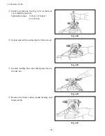
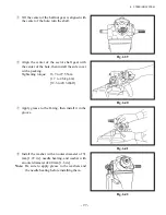
Apply grease to the inside of the slide ring, then
install it with spring.
Fig. 6.43
Fig. 6.44
Fig. 6.45
Fig. 6.46
⑩
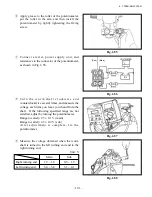
Install the set plate jig.
Tightening torque: 44 N-m {4.5 kgf-m}
[32.5 lbf-ft]
⑪
Install the washer with an outer diameter of 40
mm [1.6 in.], needle bearing, and washer with
an outer diameter of 31 mm [1.22 in.].
Note:
Apply grease to the washers and the needle
bearing before installing them.
⑫
As shown in Fig. 6.46, temporarily install
the pitman arm, and turn the worm shaft
counterclockwise. Keeping them as they are,
lightly tighten the nut by hand.
Summary of Contents for FB10-7
Page 2: ......
Page 4: ...No SEB 81BBE...
Page 8: ...No SEB 81BBE...
Page 9: ...No SEB 81BBE Fig 1 Overall Dimensions Unit mm in...
Page 10: ...No SEB 81BBE...
Page 28: ...1 BATTERY AND CHARGER 16 NOTE...
Page 30: ...2 MOTORS 18 DRIVE UNIT Fig 2 1 Drive Motor Installation DRIVE AXLE DRIVE MOTOR...
Page 42: ...3 CONTROL SYSTEM 30 Fig 3 2 Inverter Assembly 1 0 to 2 5 ton Trucks...
Page 43: ...31 3 CONTROL SYSTEM Fig 3 3 Inverter Assembly 3 0 to 3 5 ton Trucks...
Page 44: ...3 CONTROL SYSTEM 32 Fig 3 4 Controller Wiring 1 0 to 2 5 ton Trucks...
Page 45: ...33 3 CONTROL SYSTEM Fig 3 5 Controller Wiring 3 0 to 3 5 ton Trucks...
Page 133: ...7 HYDRAULIC SYSTEM 121 Fig 7 27 Remove the oil seal from the front cover...
Page 160: ...8 LOAD HANDLING SYSTEM 148 NOTE...


