6. STEERING SYSTEM
- 101 -
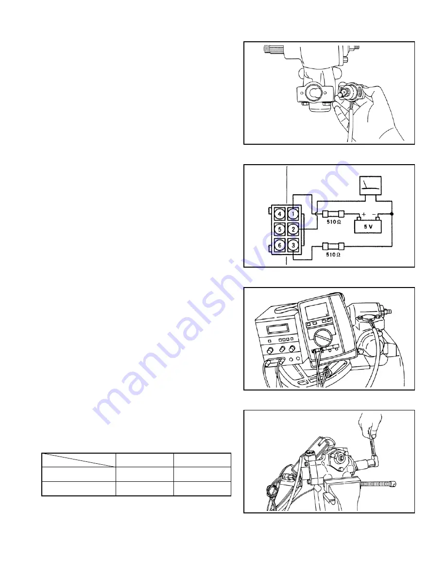
Fig. 6.55
Fig. 6.56
Fig. 6.57
Fig. 6.58
⑥
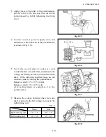
Apply grease to the roller of the potentiometer,
put the roller in the arm, and then install the
potentiometer by lightly tightening the fixing
screw.
⑦
Connect a tester, power supply unit, and
resistances to the connector of the potentiometer,
as shown in Fig. 6.56.
⑧
T u r n t h e w o r m s h a f t c l o c k w i s e a n d
counterclockwise several times, and measure the
voltage each time you leave your hand from the
shaft. If the following specified range are not
satisfied, adjust by turning the potentiometer.
Range to satisfy: 2.5 ± 0.1 V (main)
Range to satisfy: 2.5 ± 0.4 V (sub)
A f t e r a d j u s t m e n t i s c o m p l e t e , f i x t h e
potentiometer.
⑨
Measure the voltage obtained when the worm
shaft is turned to the left turning end and to the
right turning end.
Unit: V
Main
Sub
Right turning end
1.2 – 1.6
0.9 – 1.9
Left turning end
3.4 – 3.8
3.1 – 4.1
VOLTMETER
(Sub)
(Main)
Summary of Contents for FB10-7
Page 2: ......
Page 4: ...No SEB 81BBE...
Page 8: ...No SEB 81BBE...
Page 9: ...No SEB 81BBE Fig 1 Overall Dimensions Unit mm in...
Page 10: ...No SEB 81BBE...
Page 28: ...1 BATTERY AND CHARGER 16 NOTE...
Page 30: ...2 MOTORS 18 DRIVE UNIT Fig 2 1 Drive Motor Installation DRIVE AXLE DRIVE MOTOR...
Page 42: ...3 CONTROL SYSTEM 30 Fig 3 2 Inverter Assembly 1 0 to 2 5 ton Trucks...
Page 43: ...31 3 CONTROL SYSTEM Fig 3 3 Inverter Assembly 3 0 to 3 5 ton Trucks...
Page 44: ...3 CONTROL SYSTEM 32 Fig 3 4 Controller Wiring 1 0 to 2 5 ton Trucks...
Page 45: ...33 3 CONTROL SYSTEM Fig 3 5 Controller Wiring 3 0 to 3 5 ton Trucks...
Page 133: ...7 HYDRAULIC SYSTEM 121 Fig 7 27 Remove the oil seal from the front cover...
Page 160: ...8 LOAD HANDLING SYSTEM 148 NOTE...


